Blue Gold Water Maker OLD MODELS DOCUMENTS


You can view and download a quick reference sheets for mounting the components and wiring the cables.

Quick Reference Sheets


Water Maker Schematic Wiring Diagrams

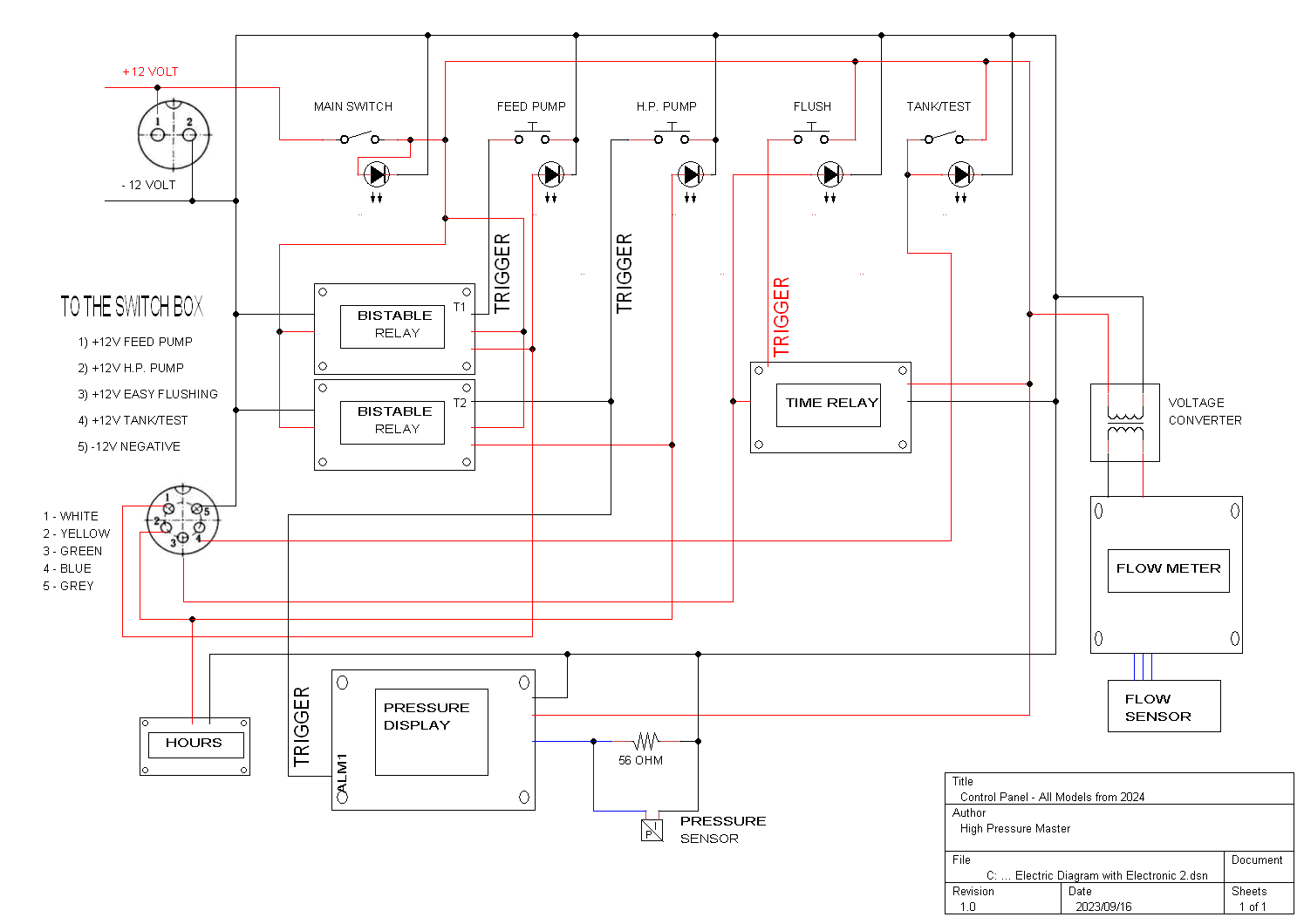
Control Panel - All Models from 2024
Control Panel – All Models from 2024
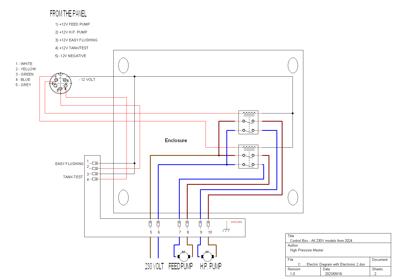
Control Box - All 230V models from 2024
Control Box – All 230V models from 2024
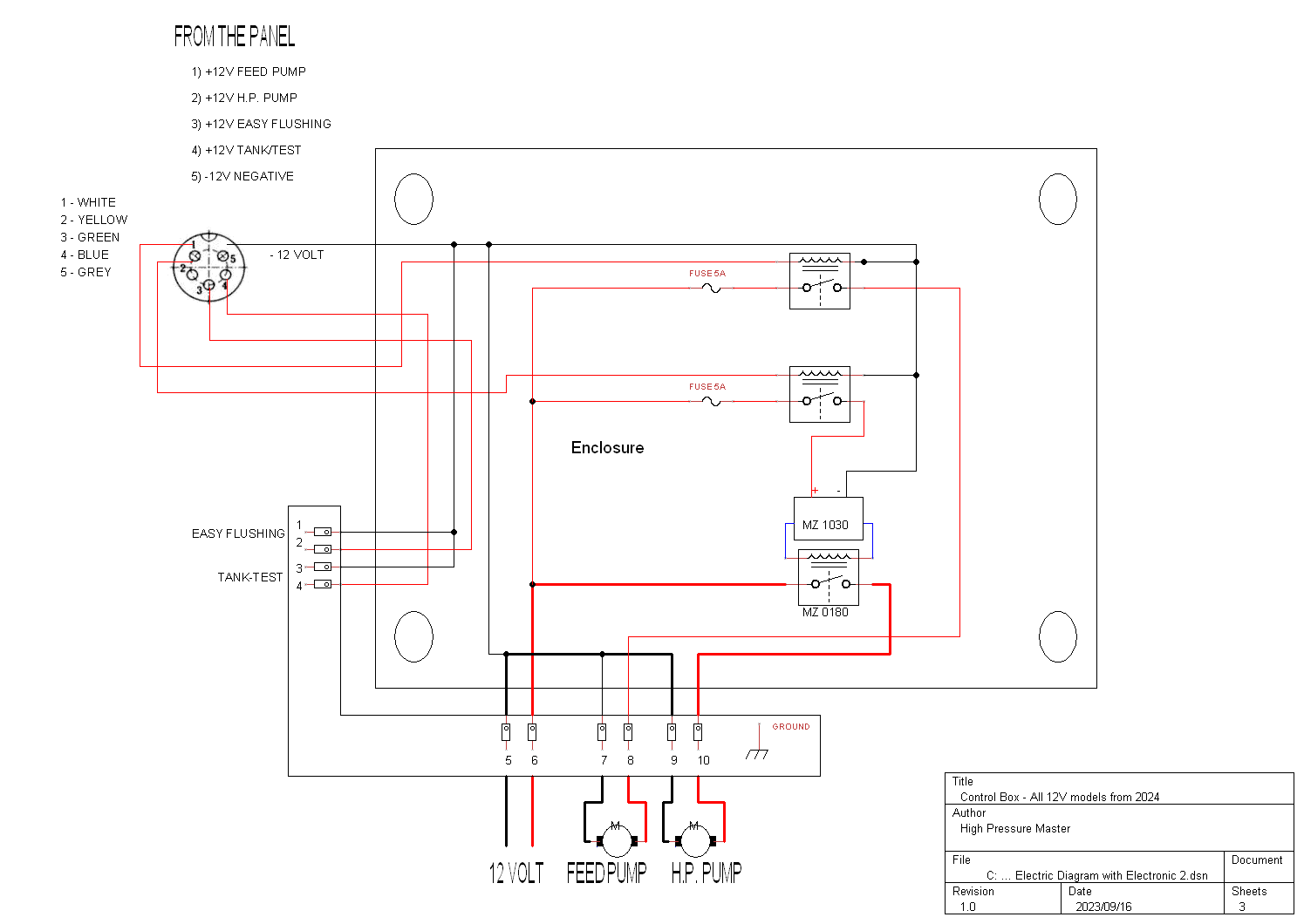
Control Box - All 12V models from 2024
Control Box – All 12V models from 2024
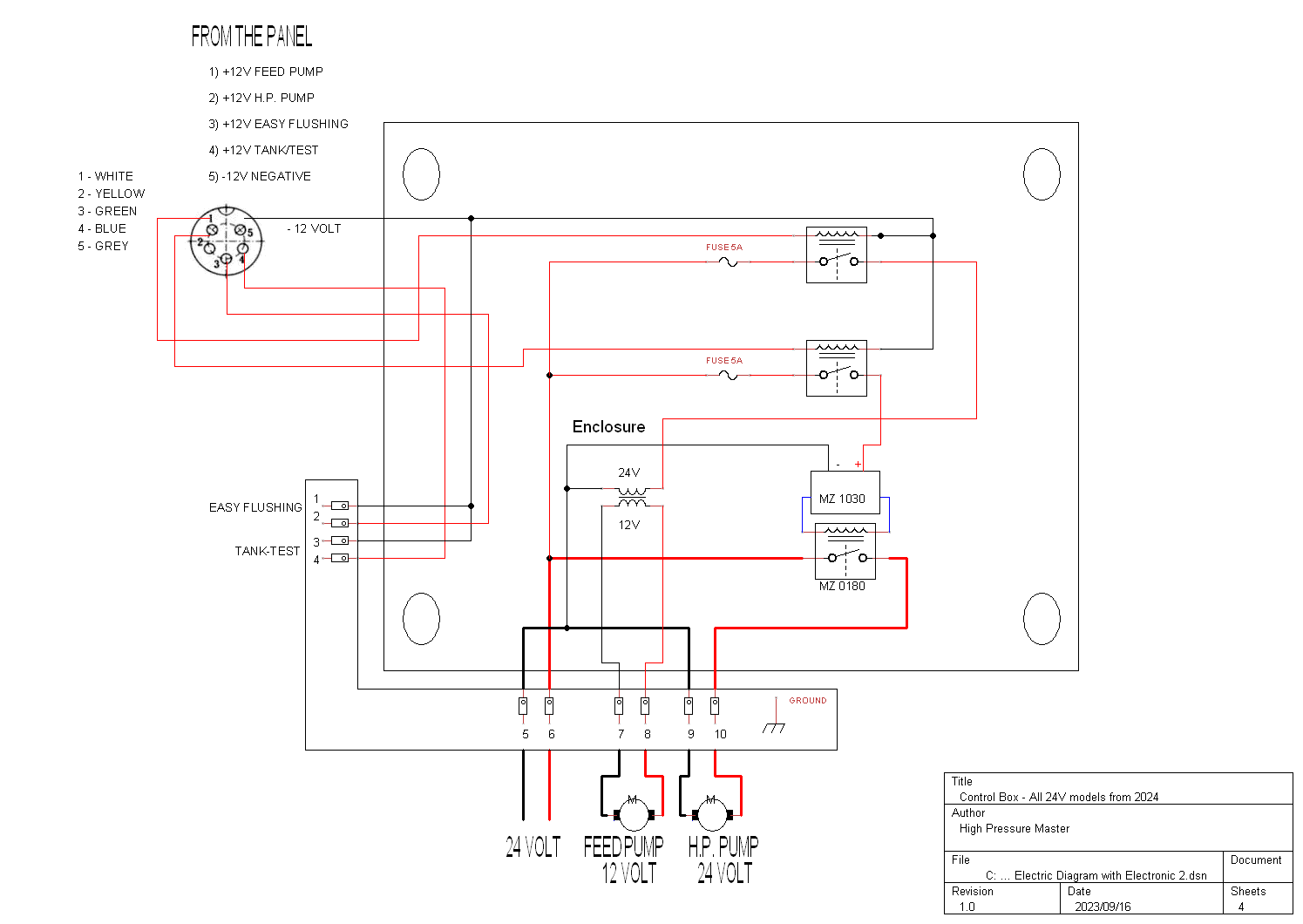
Control Box - All 24V models from 2024
Control Box – All 24V models from 2024

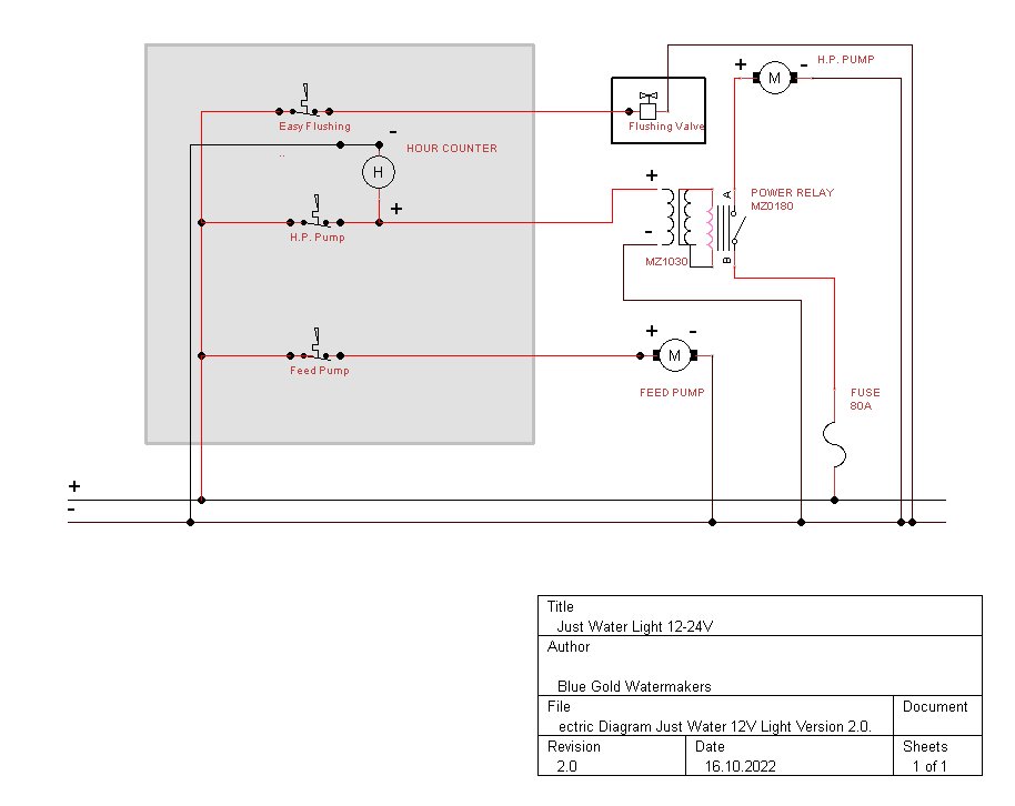
Electric Diagram Watermaker Just Water Light 12 24 Volt Rev02 - Alte Modelle

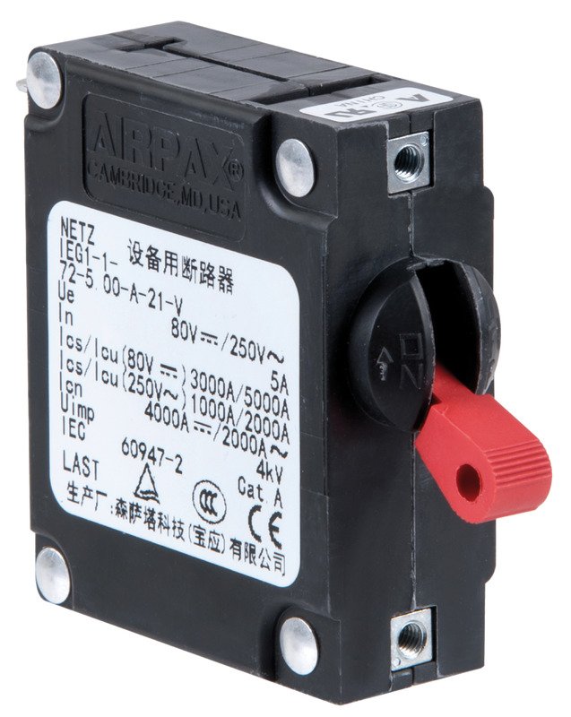
The switches are 5 Amperes SENSATA AIRPAX toggle handle hydraulic magnetic circuit breaker with rechargeable automatic fuse.

Designed on purpose for the marine environment. In case of heavy overload (i.e.: short circuits), the circuit breaker disconnects instantaneously; for overloads up to 50% it maintains the contact for few seconds so, in case it is due to a chance event, it has time to return within the limits without interrupting the power supply. In case of short circuit, the switch cannot be reactivated until the problem is solved.

AIRPAX SENSATA - Alte Modelle

sensata-LEJ-LEJA-series-hydraulic-magnetic-circuit-protectors-datasheet.pdf

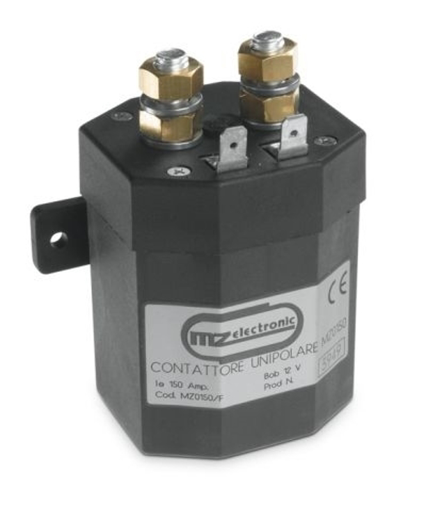
0001538 mz contactor unipolar 12v 200a mz0180f 7501 - Alte Modelle
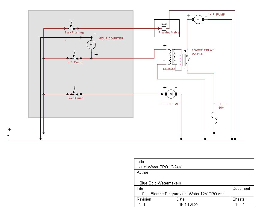
Regarding the MZ0180 Power Relay + MZ1030 Adapter for single-pole Contactors please refer to the dedicated post.


IMPORTANT: For the power line to the motor of the high pressure pump, please use a 35 mm2 electric cable and keep it as short as possible.


Electric Diagram Watermaker Just Water PRO 12 24 Volt Rev02 - Alte Modelle

The switches are 5 Amperes SENSATA AIRPAX toggle handle hydraulic magnetic circuit breaker with rechargeable automatic fuse.

Designed on purpose for the marine environment. In case of heavy overload (i.e.: short circuits), the circuit breaker disconnects instantaneously; for overloads up to 50% it maintains the contact for few seconds so, in case it is due to a chance event, it has time to return within the limits without interrupting the power supply. In case of short circuit, the switch cannot be reactivated until the problem is solved.

AIRPAX SENSATA - Alte Modelle

sensata-LEJ-LEJA-series-hydraulic-magnetic-circuit-protectors-datasheet.pdf

0001538 mz contactor unipolar 12v 200a mz0180f 7501 - Alte Modelle
Regarding the MZ0180 Power Relay + MZ1030 Adapter for single-pole Contactors please refer to the dedicated post.


IMPORTANT: For the power line to the motor of the high pressure pump, please use a 35 mm2 electric cable and keep it as short as possible.


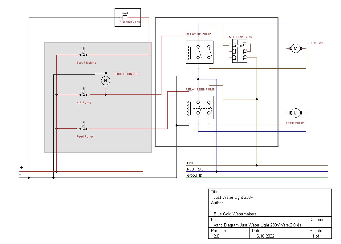
Electric Diagram Watermaker Just Water Light 230 Volt Rev02 - Alte Modelle

The switches are 5 Amperes SENSATA AIRPAX toggle handle hydraulic magnetic circuit breaker with rechargeable automatic fuse.

Designed on purpose for the marine environment. In case of heavy overload (i.e.: short circuits), the circuit breaker disconnects instantaneously; for overloads up to 50% it maintains the contact for few seconds so, in case it is due to a chance event, it has time to return within the limits without interrupting the power supply. In case of short circuit, the switch cannot be reactivated until the problem is solved.

AIRPAX SENSATA - Alte Modelle

sensata-LEJ-LEJA-series-hydraulic-magnetic-circuit-protectors-datasheet.pdf

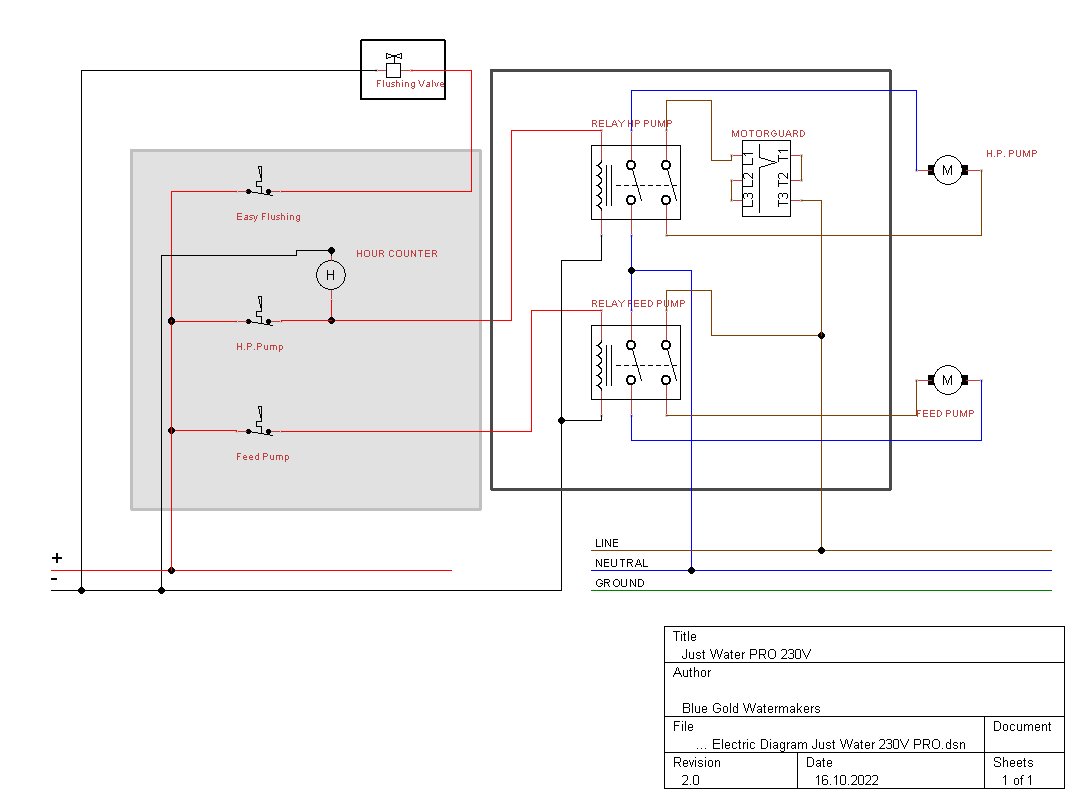
Electric Diagram Watermaker Just Water PRO 230 Volt Rev02 - Alte Modelle

The switches are 5 Amperes SENSATA AIRPAX toggle handle hydraulic magnetic circuit breaker with rechargeable automatic fuse.

Designed on purpose for the marine environment. In case of heavy overload (i.e.: short circuits), the circuit breaker disconnects instantaneously; for overloads up to 50% it maintains the contact for few seconds so, in case it is due to a chance event, it has time to return within the limits without interrupting the power supply. In case of short circuit, the switch cannot be reactivated until the problem is solved.

AIRPAX SENSATA - Alte Modelle

sensata-LEJ-LEJA-series-hydraulic-magnetic-circuit-protectors-datasheet.pdf


Boat Watermaker Just Water Manual


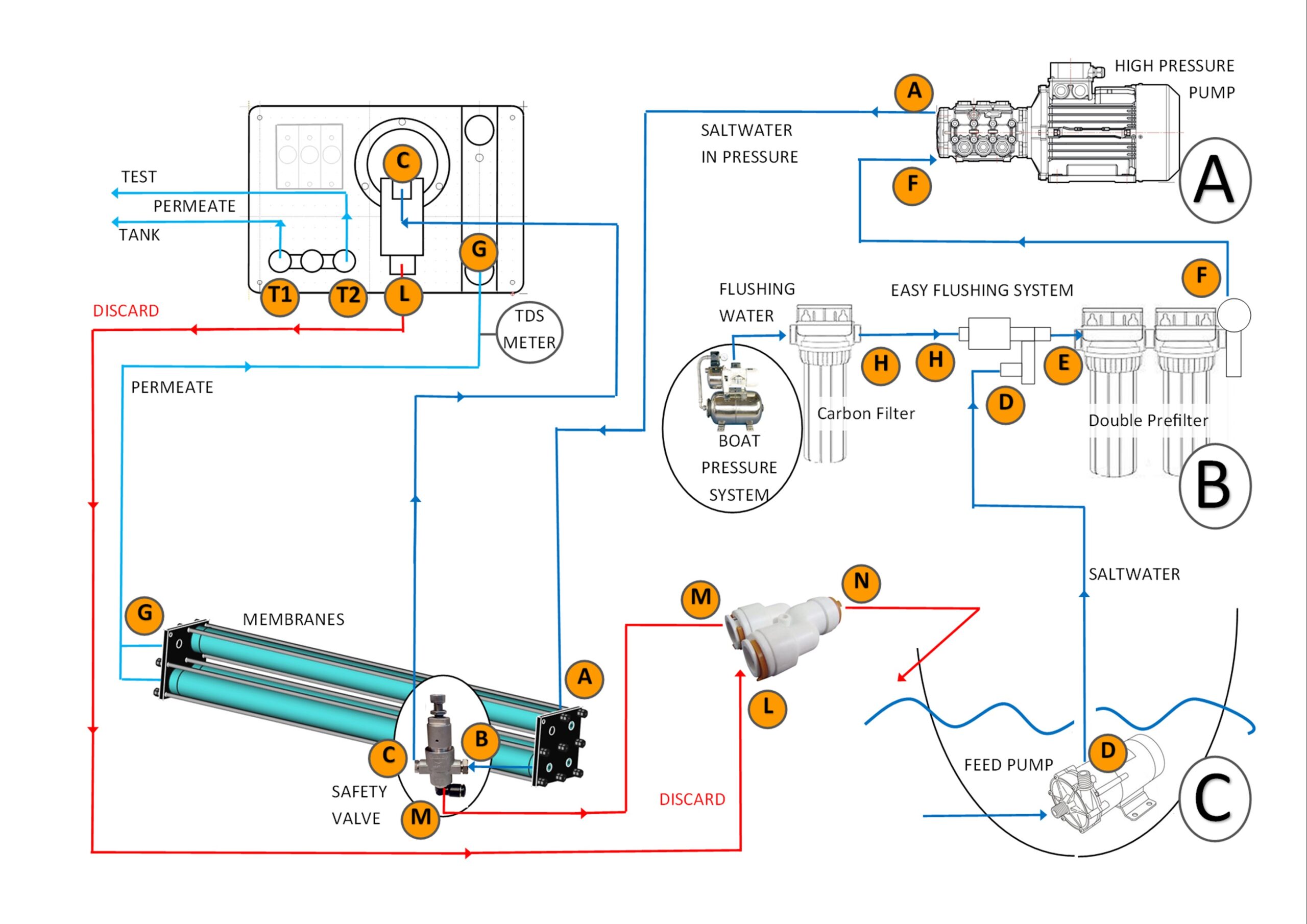
Overview of the Functioning of a Blue Gold Watermaker

page02 scaled - Alte Modelle

– The feed pump takes the seawater from the thru-hull and pulls it through a 20 mm. hose to the “Easy Flushing System” (D in the image).
– From the “Easy Flushing System” the seawater is pulled through a 20 mm. hose to the prefilter unit (E in the image) and from this one towards the inlet of the high pressure pump (F in the image).
– From the outlet of the high pressure pump, the seawater is forced to the inlet of the reverse osmosis membranes unit at a pressure of about 60 BAR (A in the image).
-The vessel/membranes assembly has two outlets:
— Saltwater, discard or brine (B in the image).
— Freshwater (G in the image).
– The brine passes through the safety valve and goes to the pressure regulation valve (C in the image). The manometer mounted together with the regulation valve shows the working pressure of the system (60 BAR max.)
– After passing through the regulation valve, the brine is sent outboard through a 16 mm. hose (L in the image). In our installation a TEE collects the brine from the regulation valve and from the safety valve (M and L in the image) and sends it outboard (N in the image).
– The freshwater (permeate) goes from the permeate outlet of the membranes assembly to the flowmeter (G in the image). Here is mounted a digital inline TDS meter for checking the quality of the produced freshwater.
– At the outlet of the flowmeter is mounted a 3-way valve, which can send the permeate towards the tank of the boat through a 13 mm. hose or towards a test outlet (T1-T2 in the image). This 3-way must never stay closed or the membranes will be damaged (we use a “T” type valve which ever allows the flow to one of the two direction or towards both the direction, but never remains closed).


Technical details: Blue Gold Water Maker Performance and Models

INFORMATION ON THE TECHNICAL FEATURES


12 Volt Watermakers “ZERO” (55 l/h)

Input voltage: 12/24 V DC
Motors:
– M80.H70 12 Volt – 1250 rpm – 30 Ampere
Noise level: 68 db
Working pressure: Max. 60 Bar
Weight: ca.35 Kg
Seawater inlet pressure: 0,5 – 4,0 Bar
Flushing pressure: 1,0 – 4,0 Bar
Standard pre-filtration: 10”DOE – 5 Micron
Permeate TDS: < 500 ppm
Salt rejection: 99,4%
Seawater pH range :2 – 11
Seawater temperature range: +5 °C – +38 °C
Chlorine tolerance: < 0,1 ppm
Continuous operation: Max 40°C ambient temperature
RO Membranes:
-1 x Seawater Element (2,5” x 40”)
Water maker production amount*:
-55 Liters/Hour (1×2540 Membrane)
*25°C water temperature, 32000 ppm salinity, 60 bar working pressure


12/24 Volt Watermakers “JUST WATER” (60-80 l/h)

Input voltage: 12/24 V DC
Motors:
– M80.H140 12 Volt – 1700 rpm – 50 Ampere
– M80.H140 24 Volt – 1700 rpm – 34 Ampere
Noise level: 68 db
Working pressure: Max. 60 Bar
Weight: ca.35 Kg
Seawater inlet pressure: 0,5 – 4,0 Bar
Flushing pressure: 1,0 – 4,0 Bar
Standard pre-filtration: 10”DOE – 5 Micron
Permeate TDS: < 500 ppm
Salt rejection: 99,4%
Seawater pH range :2 – 11
Seawater temperature range: +5 °C – +38 °C
Chlorine tolerance: < 0,1 ppm
Continuous operation: Max 40°C ambient temperature
RO Membranes:
-1 x Seawater Element (2,5” x 40”)
-2 x Seawater Element (2,5” x 21”)
-3 x Seawater Element (2,5” x 21”)
Water maker production amount*:
-60 Liters/Hour (1×2540 Membrane)
-60 Liters/Hour (2×2521 Membranes)
-80 Liters/Hour (3×2521 Membranes)
*25°C water temperature, 32000 ppm salinity, 60 bar working pressure


230 Volt (750 Watt) Watermakers “JUST WATER” (60-80 l/h)

Input voltage: Single phase 230 Volt AC (three phases 400 Volt on request)
Motor: MEC80 – 1450 rpm – 750 Watt (1 Hp)
Noise level: 68 db
Working pressure: Max. 60 Bar
Weight: ca.35 Kg
Seawater inlet pressure: 0,5 – 4,0 Bar
Flushing pressure: 1,0 – 4,0 Bar
Standard pre-filtration: 10”DOE – 5 Micron
Permeate TDS: < 500 ppm
Salt rejection: 99,4%
Seawater pH range :2 – 11
Seawater temperature range: +5 °C – +38 °C
Chlorine tolerance: < 0,1 ppm
Continuous operation: Max 40°C ambient temperature
RO Membranes:
-1 x Seawater Element (2,5” x 40”)
-2 x Seawater Element (2,5” x 21”)
-3 x Seawater Element (2,5” x 21”)
Water maker production amount*:
-60 Liters/Hour (1×2540 Membrane)
-60 Liters/Hour (2×2521 Membranes)
-80 Liters/Hour (3×2521 Membranes)
*25°C water temperature, 32000 ppm salinity, 60 bar working pressure


230 Volt (1,1 kW) Watermakers “JUST WATER” (75-120 l/h)

Input voltage: Single phase 230 Volt AC (three phases 400 Volt on request)
Motor: MEC90 – 1450 rpm – 1100 Watt (1,5 Hp)
Noise level: 68 db
Working pressure: Max. 60 Bar
Weight: ca.40 Kg
Seawater inlet pressure: 0,5 – 4,0 Bar
Flushing pressure: 1,0 – 4,0 Bar
Standard pre-filtration: 10”DOE – 20+5 Micron
Permeate TDS: < 500 ppm
Salt rejection: 99,4%
Seawater pH range :2 – 11
Seawater temperature range: +5 °C – +38 °C
Chlorine tolerance: < 0,1 ppm
Continuous operation: Max 40°C ambient temperature
RO Membranes:
-1 x Seawater Element (2,5” x 40”)
-2 x Seawater Element (2,5” x 40”)
Water maker production amount*:
-75 Liters/Hour (1×2540 Membrane)
-120 Liters/Hour (2×2540 Membranes)
*25°C water temperature, 32000 ppm salinity, 60 bar working pressure


230 Volt (1,5 kW) Watermakers “JUST WATER” (90-150 l/h)

Input voltage: Single phase 230 Volt AC (three phases 400 Volt on request)
Motor: MEC90 – 1450 rpm – 1500 Watt (2 Hp)
Noise level: 68 db
Working pressure: Max. 60 Bar
Weight: ca.40 Kg
Seawater inlet pressure: 0,5 – 4,0 Bar
Flushing pressure: 1,0 – 4,0 Bar
Standard pre-filtration: 10”DOE – 20+5 Micron
Permeate TDS: < 500 ppm
Salt rejection: 99,4%
Seawater pH range :2 – 11
Seawater temperature range: +5 °C – +38 °C
Chlorine tolerance: < 0,1 ppm
Continuous operation: Max 40°C ambient temperature
RO Membranes:
-1 x Seawater Element (2,5” x 40”)
-2 x Seawater Element (2,5” x 40”)
Water maker production amount*:
-90 Liters/Hour (1×2540 Membrane)
-150 Liters/Hour (2×2540 Membranes)
*25°C water temperature, 32000 ppm salinity, 60 bar working pressure


230 Volt (2,2 kW) Watermakers “JUST WATER” (200-250 l/h)

Input voltage: Single phase 230 Volt AC (three phases 400 Volt on request)
Motor: MEC90 – 1450 rpm – 2200 Watt (3 Hp)
Noise level: 68 db
Working pressure: Max. 60 Bar
Weight: ca.45 Kg
Seawater inlet pressure: 0,5 – 4,0 Bar
Flushing pressure: 1,0 – 4,0 Bar
Standard pre-filtration: 10”DOE – 20+5 Micron
Permeate TDS: < 500 ppm
Salt rejection: 99,4%
Seawater pH range :2 – 11
Seawater temperature range: +5 °C – +38 °C
Chlorine tolerance: < 0,1 ppm
Continuous operation: Max 40°C ambient temperature
RO Membranes:
-3 x Seawater Element (2,5” x 40”)
-4 x Seawater Element (2,5” x 40”)
Water maker production amount*:
-200 Liters/Hour (3×2540 Membrane)
-250 Liters/Hour (4×2540 Membranes)
*25°C water temperature, 32000 ppm salinity, 60 bar working pressure

Several optional extensions and customizations can be made to our watermakers. Every boat is different and every boat owner has personal needs.
We can meet these needs and make suitable machines for individual customer needs.

WHAT CAN THE JUST WATER WATERMAKER DO

Your Blue Gold JUST WATER Watermaker is a watermaker that can produce fresh or drinking water from seawater by reverse osmosis.
The modular design allows for decentralized installation of its individual components to give you many options when it comes to space. The reverse osmosis membranes have a service life of approx. 1000 operating hours. The pre-filters, depending on the degree of contamination of the seawater, approx.50-100 operating hours.

BASIC INFORMATION ON THE PRODUCTION OF DRINKING WATER

Drinking water extraction is necessary wherever no drinking water is available from the tap/supply system. The aim of reverse osmosis is to reduce the components dissolved in seawater to a minimum. The “produced” freshwater is characterized by a very good drinking quality and is completely free of bacteria and viruses. Thus, it meets the highest standards and can be used for pure consumption as well as for the preparation of food and beverages.

THIS IS HOW DRINKING WATER PRODUCTION WITH THE HELP OF DESALINATION PLANTS WORKS

Seawater is forced at high pressure through one or more membranes that act as “molecular sieves” and allow only pure freshwater to pass through. Most dissolved solid particles do not pass through the membranes. The membrane is automatically cleaned by the system with seawater.
Not all particles dissolved in seawater can be filtered out. The system is designed to reject 99.4% of TDS (Totally Dissolved Solids); approximately 2% of the 35000 PPM/TDS passes through the membranes. This ensures drinking water with a TDS value of <500 ppm. A value <300 ppm is considered very good in the taste assessment.
Please note that the drinking water produced by your reverse osmosis system is essentially sterile. However, your fresh water tank should be treated periodically with an appropriate dose of chlorine to ensure that it remains consumable.
We suggest to collect the drinking water in bottles and not to send it to the tank. You can use the test outlet to fill your bottles. This way you can separate the drinking water from the water for the showers and other uses.

A membrane unit can be fed by several pumps with different flow rates to achieve several outputs of freshwater.
The higher the productivity we want to achieve, the higher the pump flow rate will have to be, and thus also the electrical power required


Let’s start by describing which pumps can be applied to our membrane racks and see how much freshwater can be produced and what electrical power needs to be committed
Please note that these calculations are theoretical with pressures of 60 bar, water temperature of 25 degrees Celsius, and salinity of 32000 PPM. Although they fairly closely reflect practical results, a +/- 10% difference in productivity is to be considered perfectly normal.


Single membrane 2540 or two membranes 2521

The smallest of our pumps which can be coupled to a single 2540 membrane is a 4 l/h pump.
We couple this pump to a special 12-volt motor which limits its flow rate to 3.5 l/h and by absorbing only 370 Watts (30 Amperes) allows it to produce 55 l/h of freshwater.
This is our Watermaker model “ZERO” 12v watermaker for sailboat - best marine water maker - 12 volt watermakers for sailboats , and you can see it here

The same pump applied to another special motor that increases the flow rate to 4.8 l/min, using the same 2540 membrane, allows a production of more than 60 l/h with a power consumption of 550 Watts (about 46 Amperes @ 12Volt).
The same result is achieved by coupling our 5.7 l/min stainless steel pump with a motor that limits its flow rate to 4.8 l/min.
This is our series of Watermakers “Just Water” and it can be seen here.

Using a single phase 230V-750 Watt motor coupled with the 4 l/min high pressure pump, we can achieve 60 l/h of freshwater.
Here you can see this watermaker

Using a 8 l/min high pressure pump coupled with a single or three phase(s) 230/400V-1,1 kW motor, we can achieve 75 l/h of freshwater.
Here you can see this watermaker.

Using a 11 l/min high pressure pump coupled with a single or three phase(s) 230/400V-1,5 kW motor, we can achieve 90 l/h of freshwater.
Here you can see this watermaker.

The same results described above, can also be achieved using 2 membranes 2521 instead of one single membrane 2540. This solution is a little more expensive but it has the advantage of taking up less space aboard.


Two membranes 2540

Using a 8 l/min high pressure pump coupled with a single or three phase(s) 230/400V-1,1 kW motor, we can achieve 120 l/h of freshwater.
Here you can see this watermaker.

Using a 11 l/min high pressure pump coupled with a single or three phase(s) 230/400V-1,5 kW motor, we can achieve 150 l/h of freshwater.
Here you can see this watermaker.


Three membranes 2540

Using a 13 l/min high pressure pump coupled with a single or three phase(s) 230/400V-2,2 kW motor, we can achieve 200 l/h of freshwater.
Here you can see this watermaker.


Four membranes 2540

Using a 13 l/min high pressure pump coupled with a single or three phase(s) 230/400V-2,2 kW motor, we can achieve 250 l/h of freshwater.
Here you can see this watermaker.


Three membranes 2521

Using a 4 l/min high pressure punp, coupled with a special motor that increases the flow rate to 4.8 l/min,  and using 3x 2521 membranes, it is allowed a production of more than 80 l/h with a power consumption of 550 Watts (about 46 Amperes @ 12Volt).
The same result is achieved by coupling our 5.7 l/min stainless steel pump with a motor that limits its flow rate to 4.8 l/min.
This is our series of Watermakers “Just Water” and it can be seen here.

Using a single phase 230V-750 Watt motor coupled with the 4 l/min high pressure pump, we can achieve 80 l/h of freshwater.
Here you can see this watermaker


Four membranes 2521

Using a 11 l/min high pressure pump coupled with a single or three phase(s) 230/400V-1,5 kW motor, we can achieve about 140 l/h of freshwater.
This Watermaker is made upon order of the client.


Vessel for Watermakers 1024 e1681144599206 - Alte Modelle

Watermakers Marine Parts and Components

The sea water intake is a very important element of the desalination plant on a board, and to realize it properly is essential. The 90% of the problems that can have a watermaker are due to an incorrect flow of salt water.

The water intake must not be shared with any other plant on the boat, it must only serve the watermaker. This is to avoid the formation of air bubbles inside the supply circuit and to ensure a correct flow.

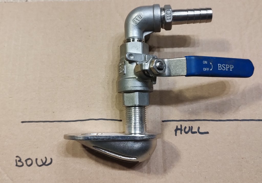
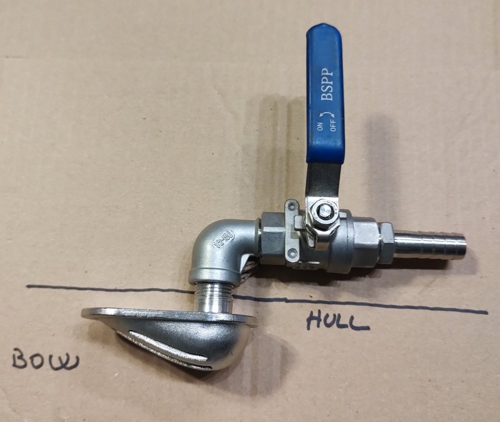
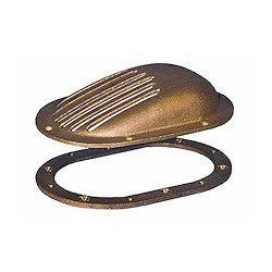
It is recommended to install a stainless steel through-hull with a grid or better a TRUDESIGN kit. The grid must be facing the bow of the boat, so that if you want to produce water while the boat is sailing, the pressure of the water will help to flood the system correctly.

The correct size of the inlet is 3/4″ and the hose barb to be used is 3/4″ x 20 mm.
A 20 mm. hose with stainless steel coil should be used throughout the supply line to the high pressure pump inlet.

Drill the hole as close as possible to the space where you are going to place the watermaker, and of course at the lowest point of the hull.

A ball valve shall be installed immediately after the sea inlet followed by an elbow with a 20mm hose barb. Using an elbow should allow the hose to run as low as possible and avoid siphoning.

As told before we suggest to use a TRUDESIGN set of fittings: https://www.trudesign.nz

Suitable for underwater use, TruDesign range of Skin Fittings are certified by the International Marine Certification Institute (IMCI) and Bureau VERITAS to ISO 9093-2.
They also comply with ABYC H-27 when used in conjunction with the TruDesign ABYC collar.

Designed and made in New Zealand, the Skin Fitting body and nut are moulded from a glass-reinforced nylon composite. High strength, high-modulus glass fibres provide dramatic strength, stiffness, toughness and dimensional stability. These properties allow a significant weight reduction over metallic fittings.
TruDesign Skin Fittings eliminate the corrosion and electrical bonding problems associated with metallic fittings.

When used in below waterline applications, a Ball Valve should be directly connected for safety and compliance to relevant marine standards.

The following pictures show how the intake looks like once the work is completed.

Bluegold watermakers seawater intake 1 - Alte Modelle Bluegold watermakers seawater intake 2 - Alte Modelle

Bluegold watermakers seawater intake 3 - Alte Modelle Bluegold watermakers seawater intake 4 - Alte Modelle

FEED PUMPS FOR SEAWATER SUPPLY

A feed pump is almost always needed to bring the salt water to the inlet of the high pressure pump.


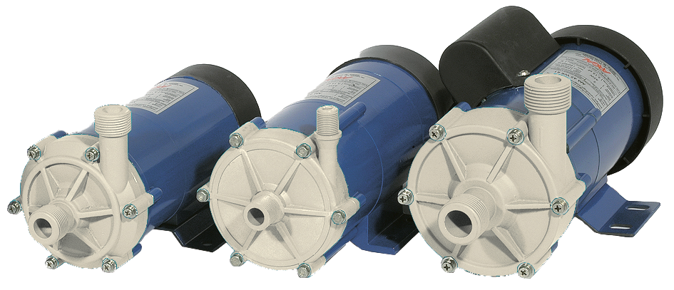
Magnetic Driven Feed Pump (not self priming)

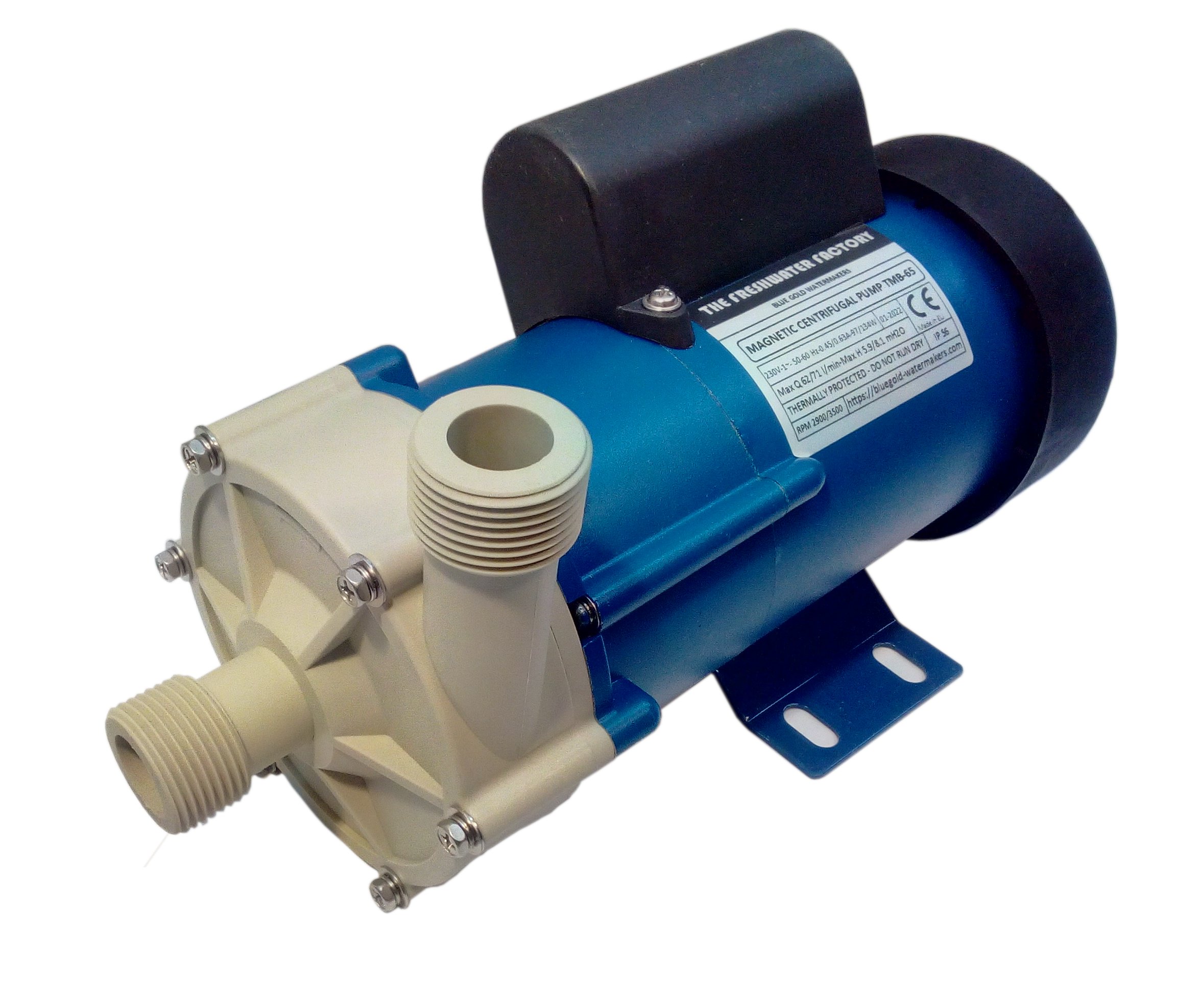
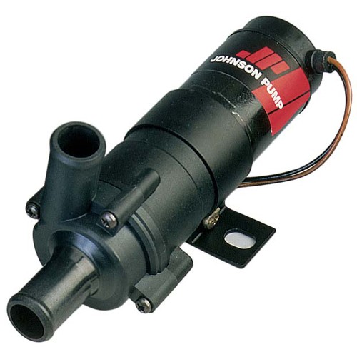
This pump must be fitted immediately after the sea water intake and its ball valve. We supply top quality magnetic drive pumps for this purpose. They are saltwater resistant and maintenance-free. The pump housing is made entirely of plastic, and there is no shaft or rotary seal between the motor and pump.

These pumps are extremely quiet and draw very small amounts of current, but they are not self-priming, so it is necessary to install them below the seawater level, immediately after the seawater inlet, taking care that they are properly flooded.

Magnetic Driven Feed Pump for Blue Gold Watermaker - Alte Modelle Johnson Pump Magnetic Driven for BlueGold Watermakers - Alte Modelle

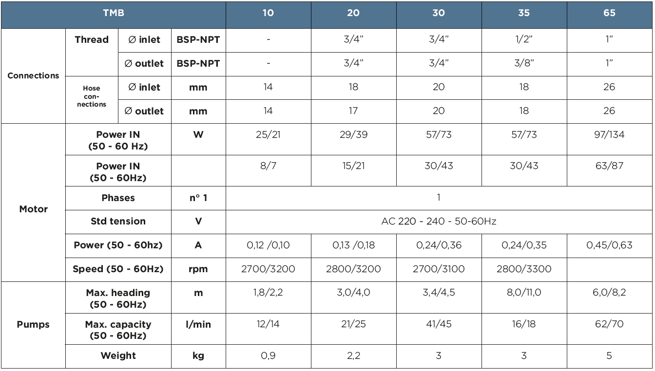
We supply 2 models of 230 V magnetic driven pumps:
TMB30 for all the applications
TMB65 for applications with longer pipes or higher heading (there is a small price difference for ordering this model).

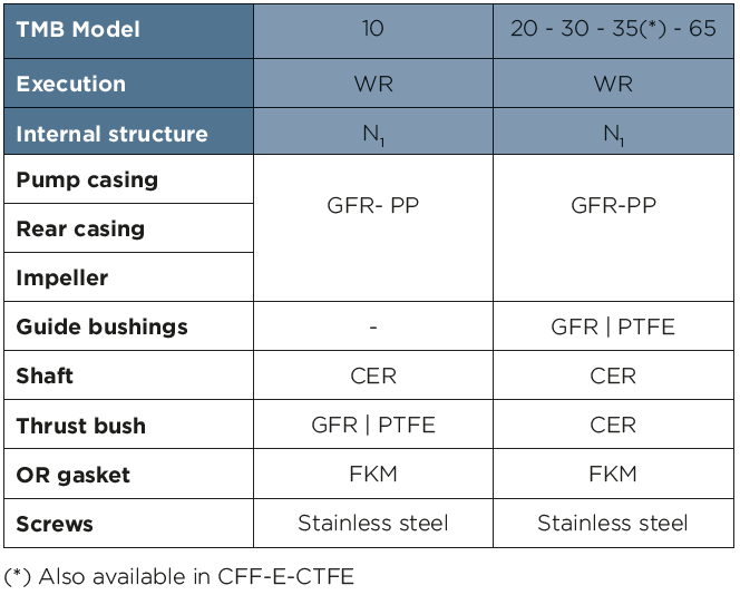
In the below tables their features and performances

BASIS connections ARGAL magnetic pumps11 - Alte Modelle

Argal Pumps centrifugal Basis trio1 - Alte Modelle

BASIS configuration ARGAL magnetic pumps1 - Alte Modelle

The models with magnetic drive do not require maintenance and are resistant to salt water. They do not need to be backwashed. This is a great advantage.


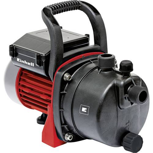
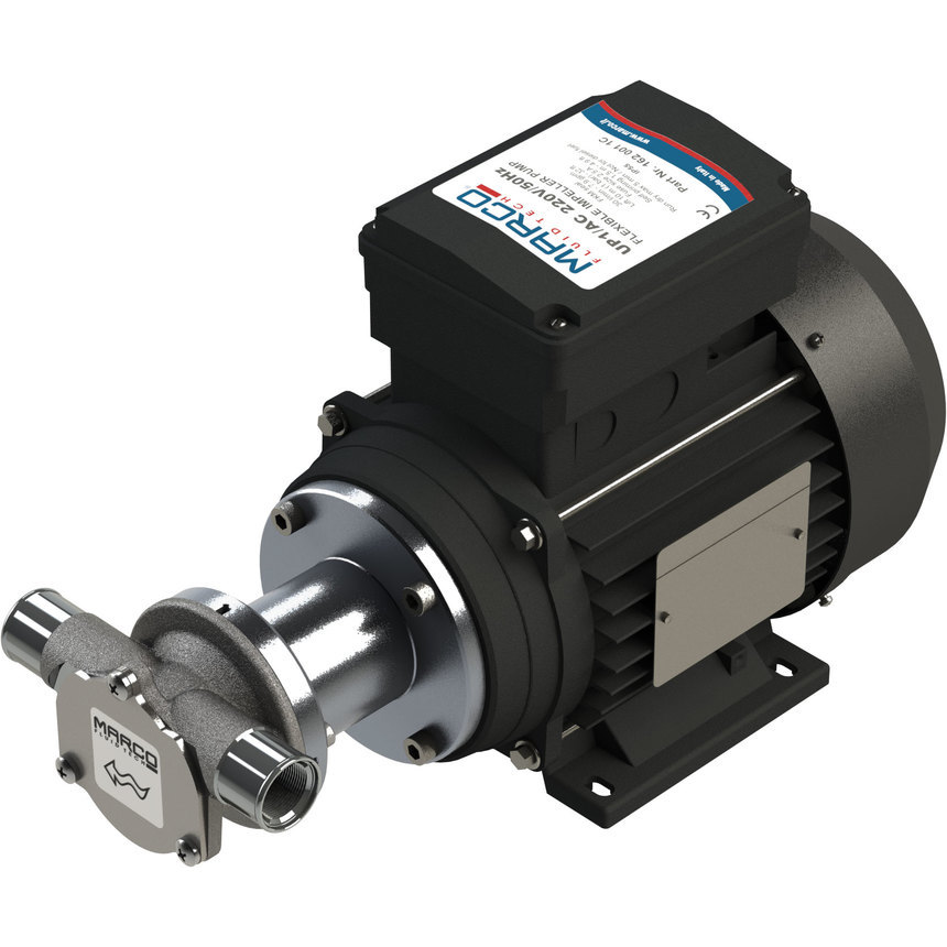
Gear or Impeller Feed Pump (self priming)

If the feed pump needs to be placed above the seawater level, a magnetic driven pump cannot be used.
In this case (please ask for a technical consultation) we can supply several kinds of pumps (centrifugal pumps, gear pumps, impeller pumps) which are self priming and can be placed above the seawater level. We suggest to wash these pumps with freshwater (especially the centrifugal and gear pumps) before decommissioning the watermaker during the winter.

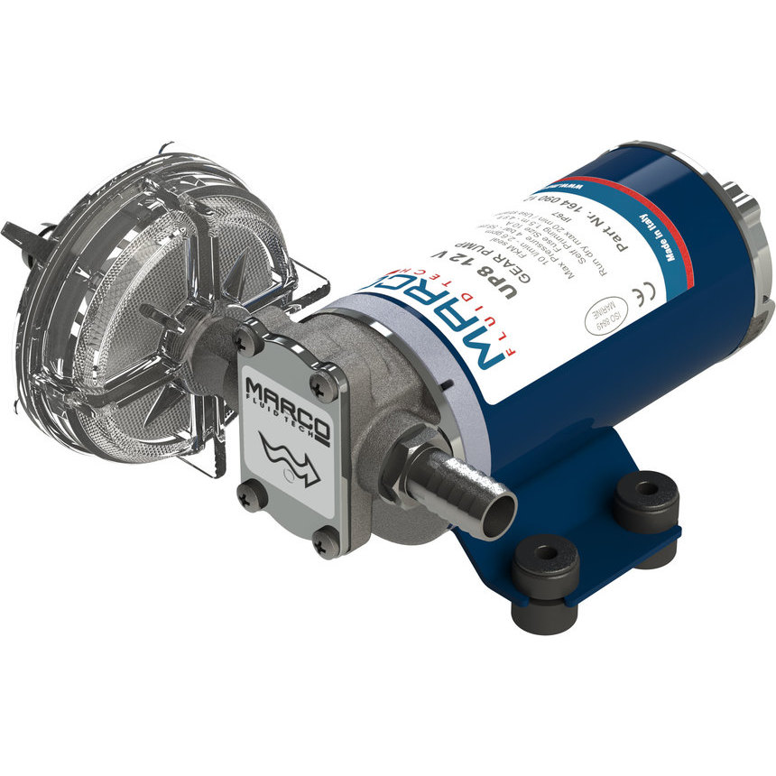
Einhell GC GP 6538 Set Gartenpumpen Set Set 3800 l h 36 m1 - Alte Modelle UP1 AC 001 - Alte ModelleUP8 001 - Alte Modelle

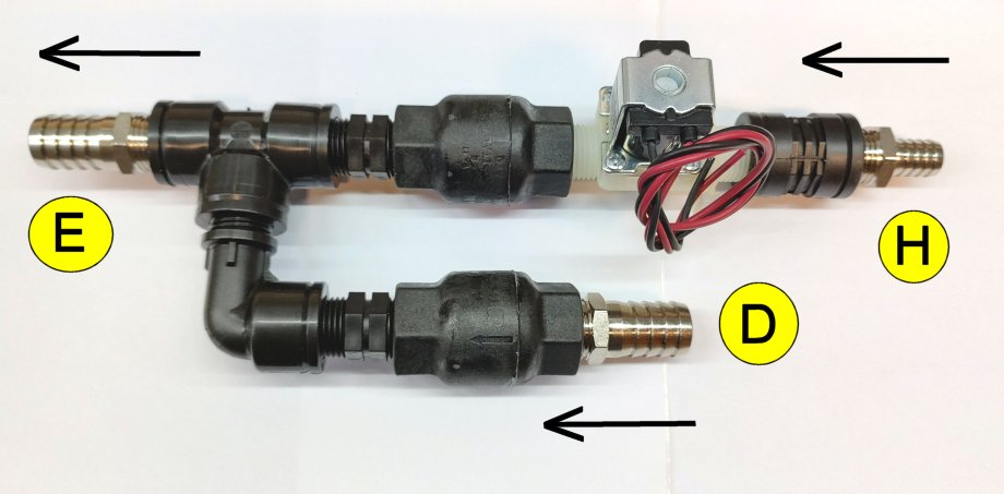
The device consists of two check valves and a solenoid valve, and is placed before the pre-filter assembly.
Here you can download the quick reference guide to see the positioning of the device in the installation of the watermaker.

Easy Flushing System Blue Gold Watermakers 2 - Alte Modelle

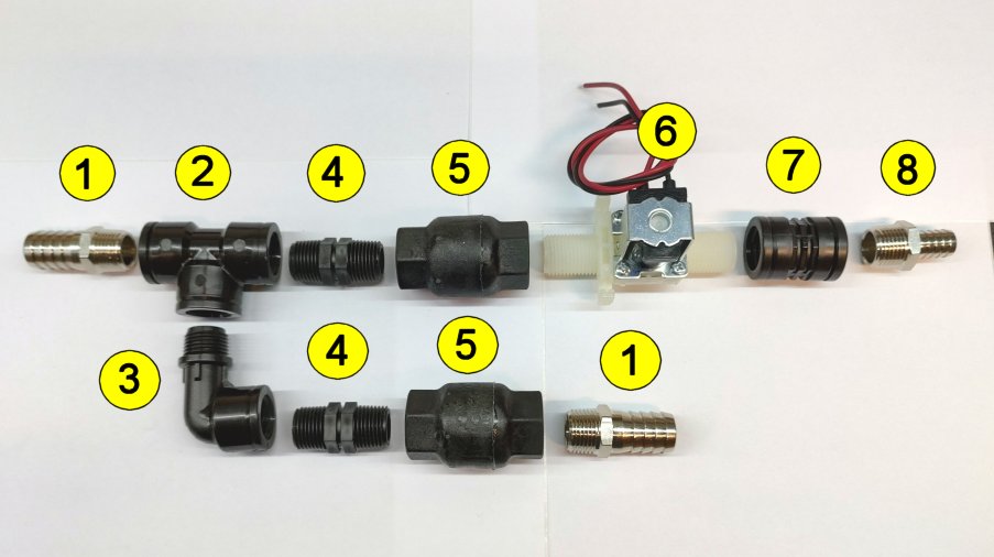
Components of the device:

E – Outlet to the prefilter unit (20 mm.)
H – Inlet from the carbon filter (13 mm.)
D – Inlet of the seawater (20 mm.)
1 – Hose adapter 1/2″x 20 mm
2 – TEE Fitting 1/2″
3 – Elbow M/F 1/2″
4 – Nipples M/M 1/2″
5 – Check Valve 1/2″ (Nylon & AISI 316L)
6 – Solenoid Valve 12V or 24V (freshwater for flushing)
7 – Nipples F/F 1/2″
8 – Hose adapter 1/2″x 13 mm

Easy Flushing System Blue Gold Watermakers 1 - Alte Modelle

Description of Functioning:

During normal operation of the watermaker, the salt water, carried by the feed pump, flows from D to E passing through the check valve 5.
The check valve 5 prevents back pressure from opening the solenoid valve 6.
The solenoid valve 6 is not engaged and remains closed: the fresh water for flushing will not flow through.

It is very important to use a check valve 5 of good quality and suitable for use with salt water. Our valves are made of nylon and fibreglass with spring and closing plate in AISI 316L stainless steel.
Do not use normal brass valves in this position, as the internal mechanism is not stainless steel and you will run into problems. These valves are not suitable for use with salt water. The same applies to valve 8.
We use a valve that opens very easily, as smaller feed pumps (12-volt models) must be able to make the water flow smoothly. It is a valve with a simple rubber flap.

During the system flushing, the solenoid valve 6 is engaged and opens. The pressure pump of the boat starts and the fresh water flows from H to E through the check valve 5. During this operation the check valve 5 prevents the fresh water from flowing back to the feed pump and mixing with the salt water here.

The system, with a focus on limiting manpower costs, is supplied as an assembly kit.
Assembling this device is elementary. Simply use Teflon tape to seal the threads, or better use Loctite 55, and match the flow direction with the flow direction indicated on both the solenoid valve and the check valves.

As can be seen, there is no timer to preset the flushing time of the system, which is always different depending on the number of membranes and the length of the hoses.

Flushing time: how to calculate it.

The time needed for rinsing a marine watermaker depends on several factors:
– the numbers of the membranes
– the length of the hoses of the plant
– the delivery of the pressure pump of the boat
– ….

therefore we cannot give a value in minutes for this time.
But there is a very simple trick to work out how long it takes to flush the system;

You can simply disconnect the reject/discard hose from the through hull and discharge the rinsing water into a bucket and constantly check its salinity by tasting it.

Once the water falling in the bucket is no longer salty at the taste, you can stop your watch and now you know how many time will it take in the future for rinsing your watermaker.

You can also know, for your information, how many liters of water are needed for the rinse.

Remember that the rinsing/flushing of the watermaker must be carried out without switching on the feed pump and the high pressure pump.

The filter elements must be installed to protect the high pressure pump and the reverse osmosis membranes.

We supply 2 kinds of prefilters, depending on the flow rate of the high pressure pump:


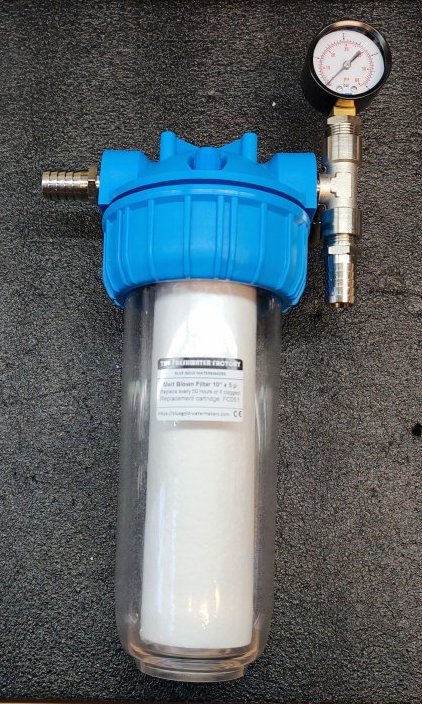
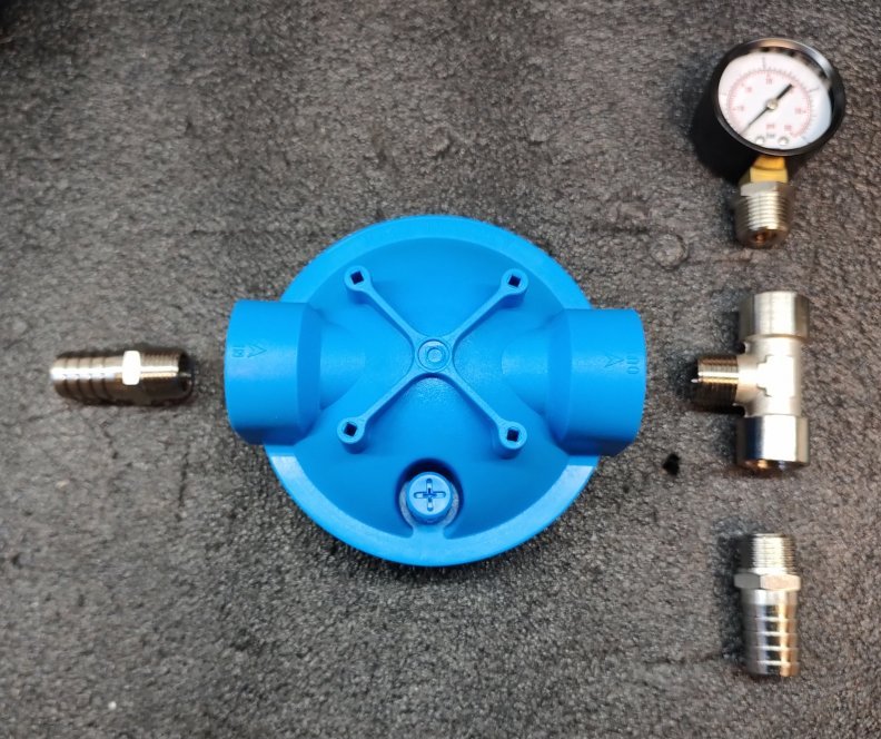
1 – Single prefilter 5 Micron x 10″ for the 12-24 Volt models and for the 230 Volt 750 Watt models.

Because of the small flow rate of this pump, a double prefilter is not needed. These smaller machines are often mounted on small boats with small spaces available, so definitely the single prefilter is the best solution. The maintenance of a single prefilter is also simpler and quicker. This prefilter is not fitted with the low pressure gauge, but if the clients wants it, we can supply it with a small surcharge.

The client will take care to assemble the provided fittings with the prefilter housing and insert the cartridge inside.

The hose adapter is for a hose with a diameter of 20 mm inside

Single prefilter for watermaker blue gold 2 - Alte Modelle  Single prefilter for watermaker blue gold 1 - Alte Modelle


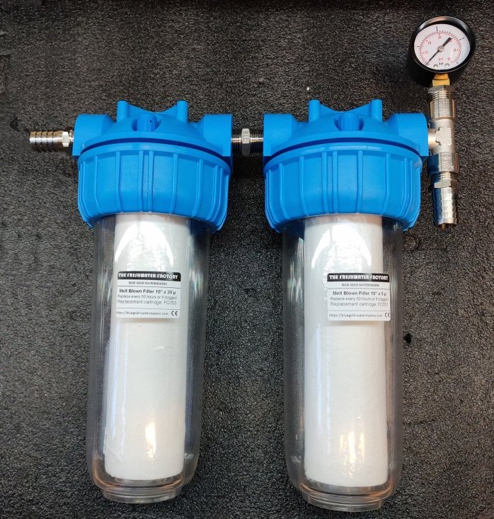
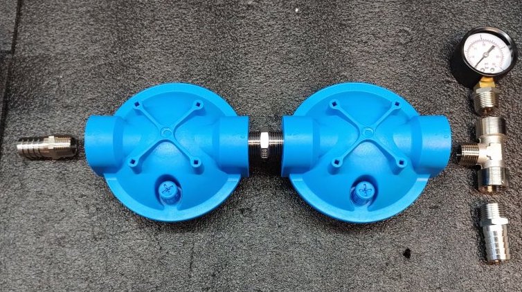
2 – Double prefilter 20+5 Micron x 10″ for all the 230 Volt 1100, 1500, 2200 Watt models.

For the bigger high pressure pumps is needed a double prefilter. A first stage with a 20 Micron cartridge, followed from a second stage with a 5 Micron cartridge.

The client will take care to assemble the provided fittings with the prefilter housings and insert the cartridges inside.

The hose adapter is for a hose with a diameter of 20 mm inside

Double prefilter for watermaker blue gold 2 - Alte Modelle Double prefilter for watermaker blue gold 1 - Alte Modelle


When positioning the prefilters, take care to leave 5 cm of gap below the container so that it can be disassembled and the cartridge can be removed.


Replacements of the cartridges

There isn’t any rule about the maintenance intervals of the filters.

It is in any case recommended to change the filters every 50/100 hours of operation. Their service life is closely related to the type of inlet water. When you remove the filter, you may notice that the color of the inner part of the cartridge is greyer than the outer part. The filter cartridge should never turn completely grey, it should be replaced before this happens.

Do not use washable filters, as they may be accidentally damaged during washing. If they are damaged, their efficiency will be compromised and the warranty for the pump will be voided.
Always use disposable polypropylene melt blown type filters with a filtration efficiency of at least 85%.

The Activated Carbon Filter removes the Chlorine from the water used to flush the membranes at the end of the desalination cycle.

If the tanks of the boat are filled both with osmosis water and water from the tap of the marina, there will be Chlorine inside, which will destroy the membranes. The activated carbon filter will stop the Chlorine.


This filter needs to be placed before the Easy Flushing System, so that all the freshwater coming from the tank of the boat and used for flushing the system is Chlorine free.


The client will take care to assemble the provided fittings with the filter housing and insert the cartridge inside.

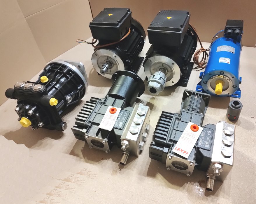
The pumps and the motors are usually shipped separately because of the weight.

The motors are weighing from 13 kg (12 Volt model) to 17 kg (230V 2200 Watt).
The motor is shipped alone, very well packed, because quite heavy, and the pump (about 5/6 kg) is shipped in another parcel with the components of the watermaker (filters, panel, hoses and fittings).
In a third parcel are shipped the vessel and the membranes.

This solution (3 parcel under 20 kg) allows the use of standard courier in EU or the Post for the shipments abroad, with the big advantage of limiting the costs for receiving the watermaker at home.

Pumps and motors Blue Gold Watermekers 1 - Alte Modelle

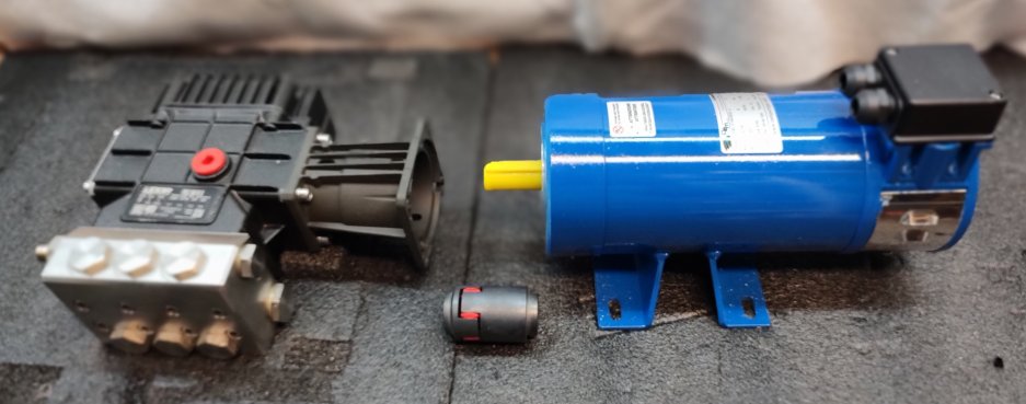
Assembling the motor with the pump is a very simple job, which requires only 5 minutes.
We show here the various type of pumps and how to mount them on a motor

In order to better understand the relationship between motors and pumps, please open the tab dedicated to the relationship between motors and pumps


Pump MIXTRON in Technopolymer

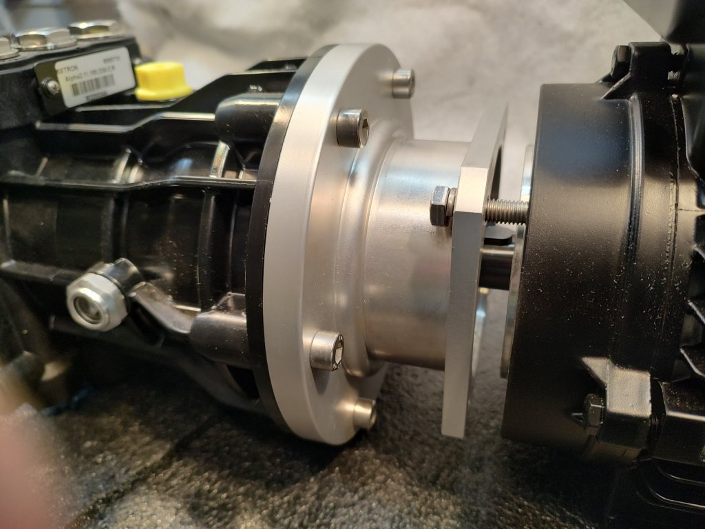
These pumps can fit our 230 Volt motors (Mec80 and Mec90) and our 12/24V motors (Mec80) directly because already built with a flange and a hollow shaft.
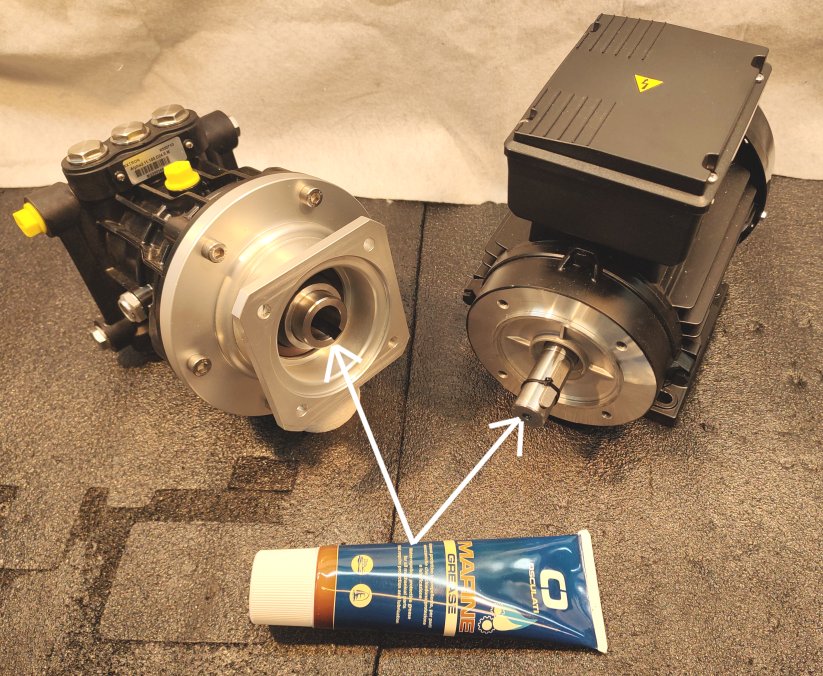
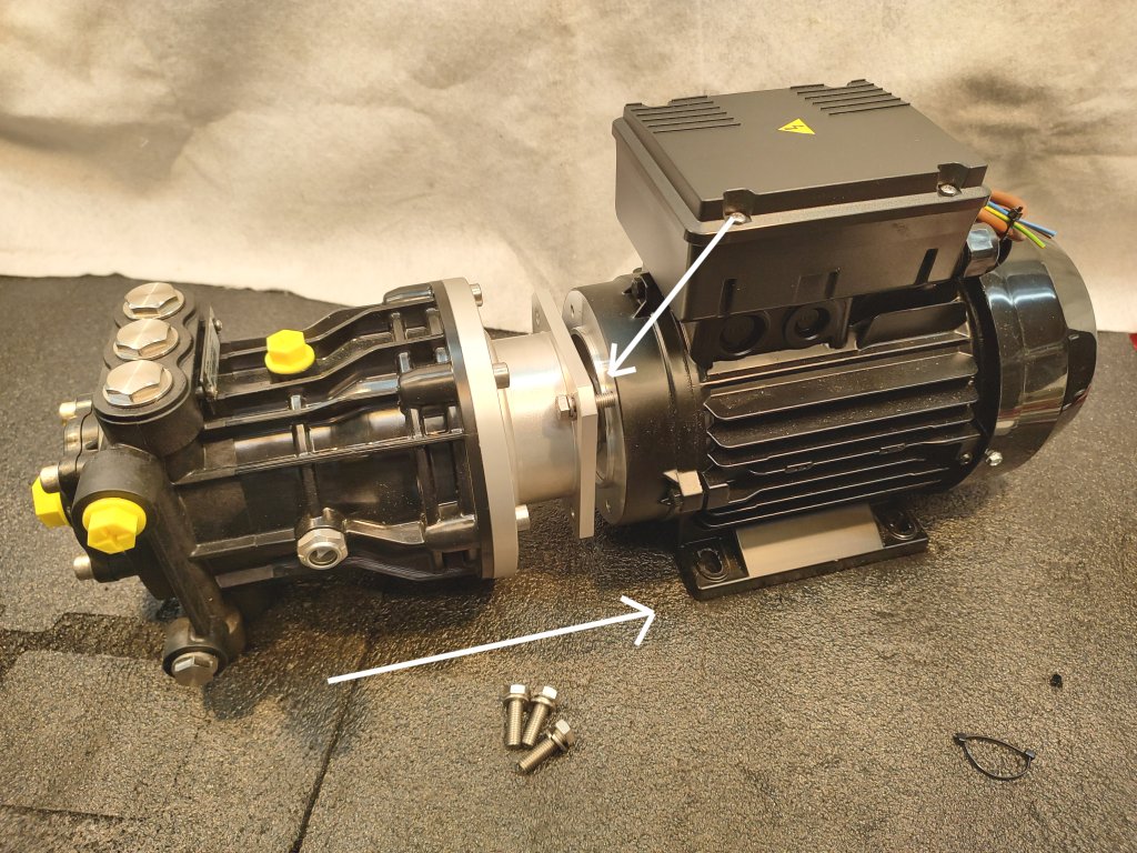
The assembling is therefore very simple. In this example we use a pump of 11 l/min and a 1500 Watt 230V Mec90 motor; for the 12/24 Volt motors the procedure is the same:

  • Put some grease on both the shafts of the motor and of the pump
  • insert the shaft of the motor in the hollow shaft of the pump
  • Fasten the flange of the pump to the flange of the motor, using the 4 screws + washer provided and tighten them
  • That’s all, the job is done!

Pumps and motors Blue Gold Watermekers 2 - Alte Modelle Pumps and motors Blue Gold Watermekers 3 - Alte Modelle Pumps and motors Blue Gold Watermekers 4 - Alte Modelle


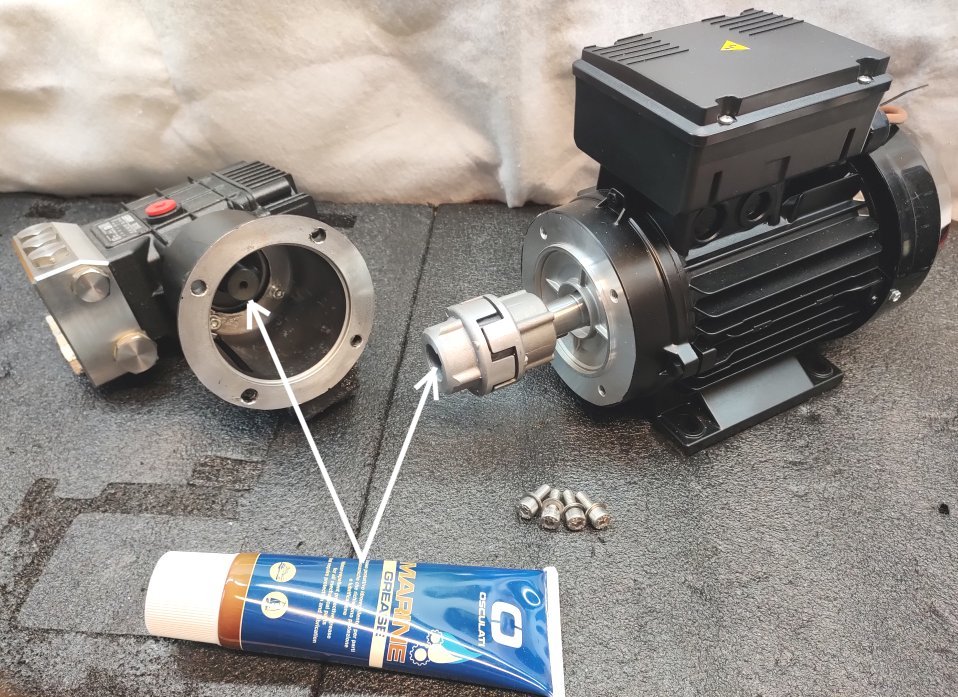
Pump UDOR in AISI 316L Stainless Steel

These pumps can fit our 230 Volt motors (Mec80 and Mec90) and our 12/24V motors (Mec80).
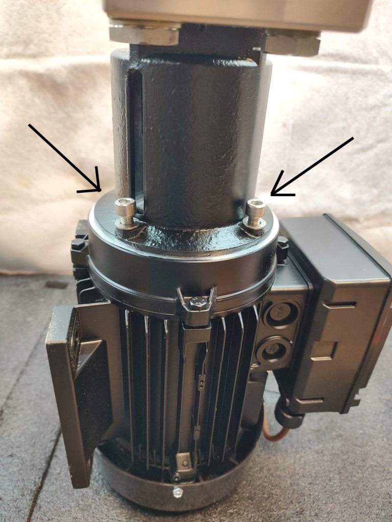
The pump is built with a male shaft, so it needs an elastic joint and a bellhousing to be coupled with the motor.

Some older models of ours used motors with hollow shaft. You can refer to the old manual about this kind of solution.

Before shipping we mount the assembly and then we separate again pump and motor.
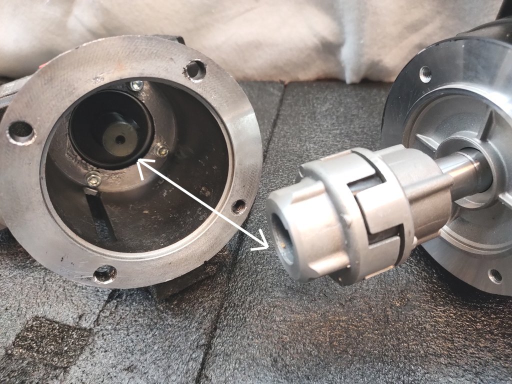
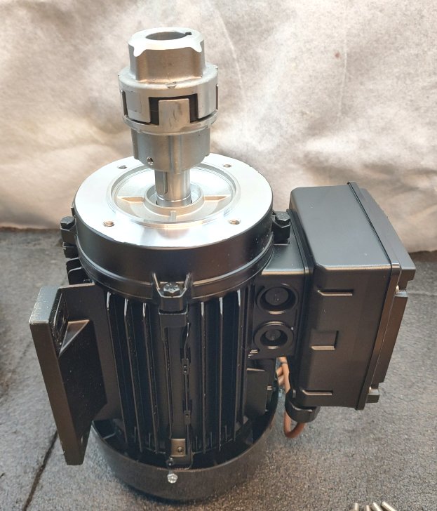
You receive the motor with the elastic joint already mounted on the shaft, and the pump with the bellhousing already mounted as well.

You have only to insert the shaft of the pump in the elastic joint.
In this example we use a pump of 11 l/min and a 1500 Watt 230V Mec90 motor; for the 12/24 Volt motors the procedure is the same, only changes the shape of some components.

  • The shaft of the pump and the elastic joint are already greased so you can proceed to the step 2
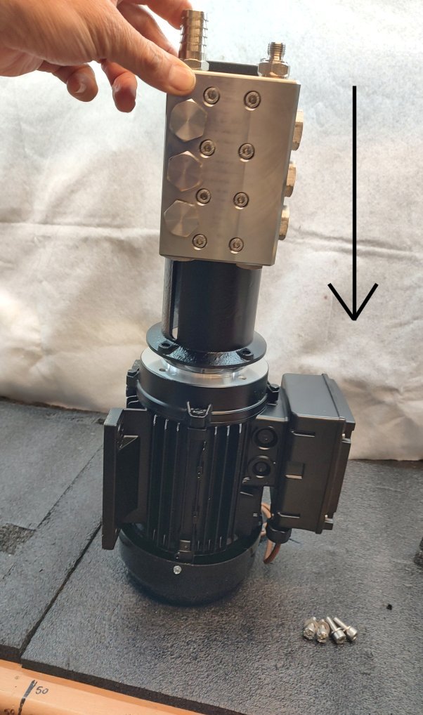
  • Put the motor standing vertical on its fan cover
  • Insert the pump from above. Pay attention to the correct orientation of the pump shaft key and its seat in the flexible coupling. This will make insertion easier.
  • Fasten the bellhousing to the flange of the motor, using the 4 screws + washer provided and tighten them
  • That’s all, the job is done!


Pumps and motors Blue Gold Watermekers 5 - Alte Modelle Pumps and motors Blue Gold Watermekers 6 - Alte Modelle
Pumps and motors Blue Gold Watermekers 7 - Alte Modelle Pumps and motors Blue Gold Watermekers 8 - Alte Modelle Pumps and motors Blue Gold Watermekers 9 - Alte Modelle


The 12/24 Volt motor

The procedure to couple the pumps to the 12/24 Volt motor is the same of the 230 Volt.
Changes only the shape of the components

Pumps and motors Blue Gold Watermekers 10 - Alte Modelle


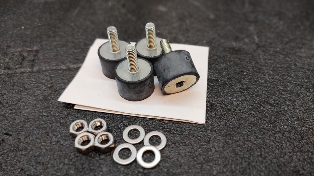
Silent Blocks

With every motor are supplied 4 vibration dampeners.
This is a small detail but very important for comfort and noise

Pumps and motors Blue Gold Watermekers 11 - Alte Modelle


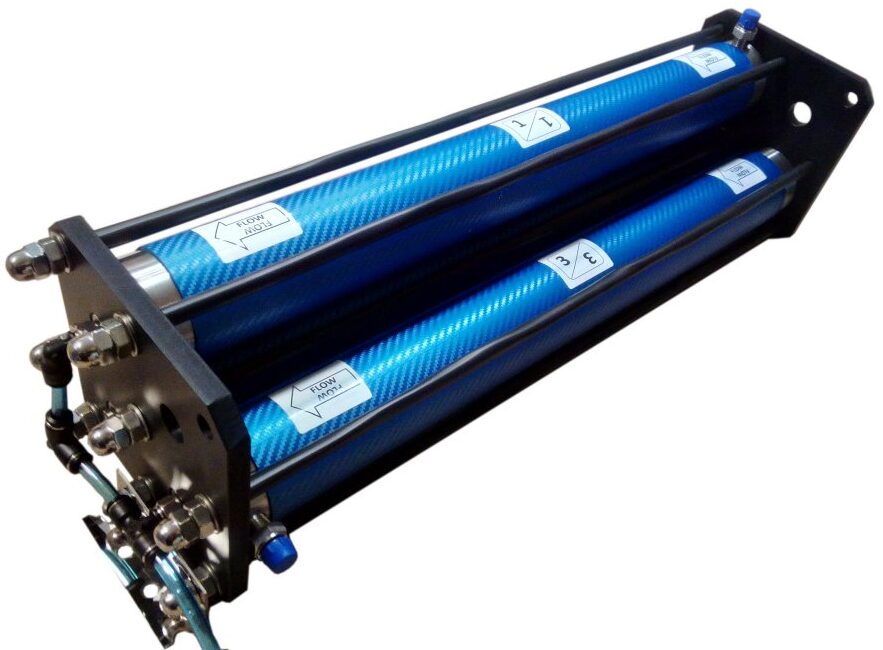
The vessels come ready-made, but still then need to know how they are made and how to insert the membranes

VIDEO TUTORIAL HERE:
https://bit2.it/membranes-mounting


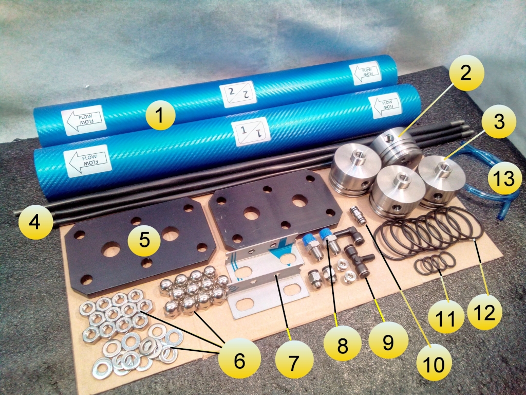
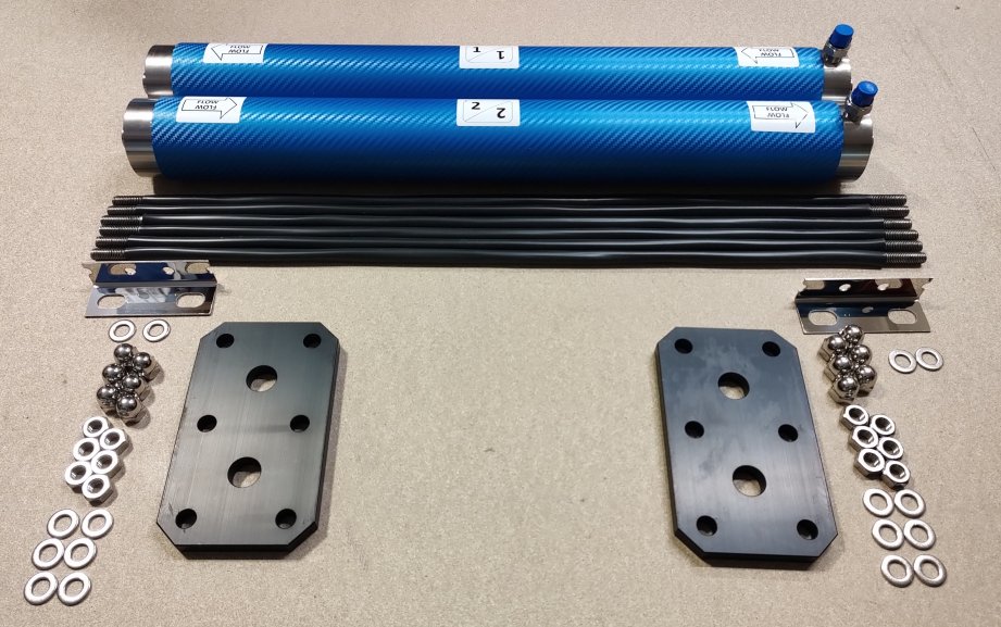
Parts of the Vessel Rack

Vessel Blue Gold Watermakers double 4 - Alte Modelle

1 – Vessel
2 – First and last heads (threaded)
3 – Intermediate heads (without thread)
4 – Bars
5 – Plates
6 – Washers and Nuts
7 – Brackets
8 – High Pressure Nipples (1/4″NPT x 1/4″ BSPP)
9 – Permeate quick fittings
10 – Nipple between the vessels
11 – Internal O-ring
12 – External O-ring
13 – Permeate hose


Preparation of the membrane vessel head

First and last head of the system
1 – Screw the high-pressure fitting into the stainless steel head.
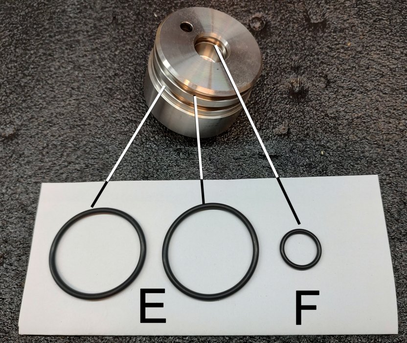
2 – Mount the two O-rings on the membrane vessel heads.
3 – Mount the O-ring on the internal side of the vessel head

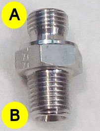
Important: the threads of the vessel head and of the nipple are NPT (conical), so in theory there is no need to use a sealant. Please use in any case one turn of Teflon tape or (better) liquid thread sealant.
The thread at the other side of the nipple is BSPP (cylindrical), and cannot get screwed into the vessel head.

Intermediate heads of the system
These heads are different and do not have any thread, because (later) they will connect the vessels over a special nipple with O-rings (n.10 in the above image).

1 – Mount the two O-rings on the membrane vessel heads.
2 – Mount the O-ring on the internal side of the vessel head

Vessel Blue Gold Watermakers Niples - Alte Modelle Vessel Blue Gold Watermakers Heads - Alte Modelle
A – 1/4″ BSPP Thread
B – 1/4″ NPT Thread
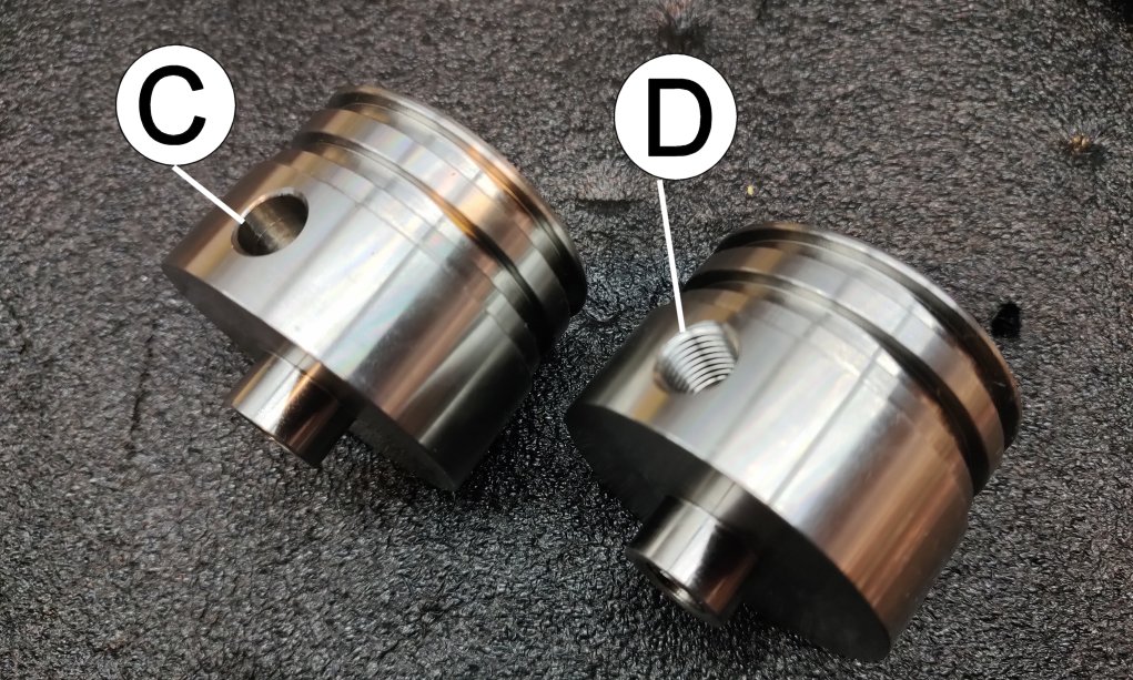
C – Intermediate Heads without thread
D – First and last heads with 1/4″NPT thread

Vessel Blue Gold Watermakers OR - Alte Modelle Vessel Blue Gold Watermakers head 2 - Alte Modelle
E – External O-ring
F – Internal O-ring
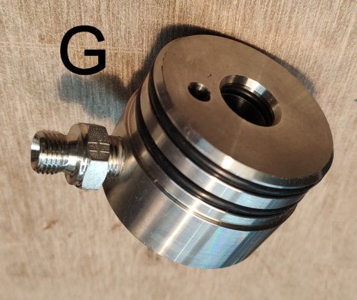
G – The head is ready


Preparation of the Vessel Pipe

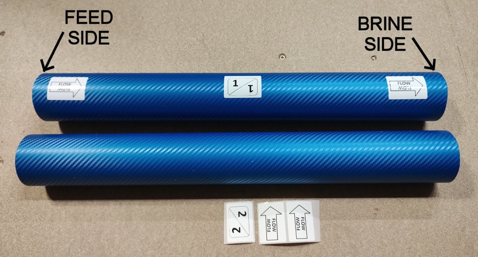
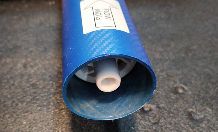
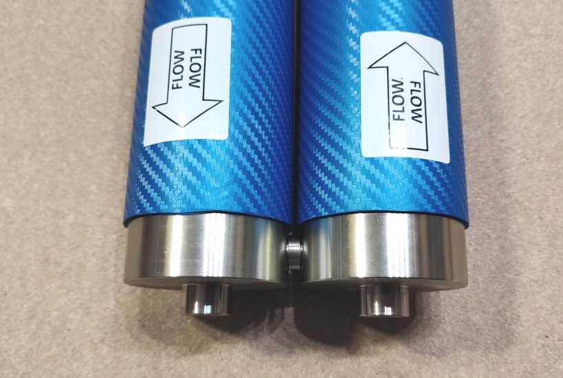
1 – Attach the stickers with the number of the vessel and the flow direction
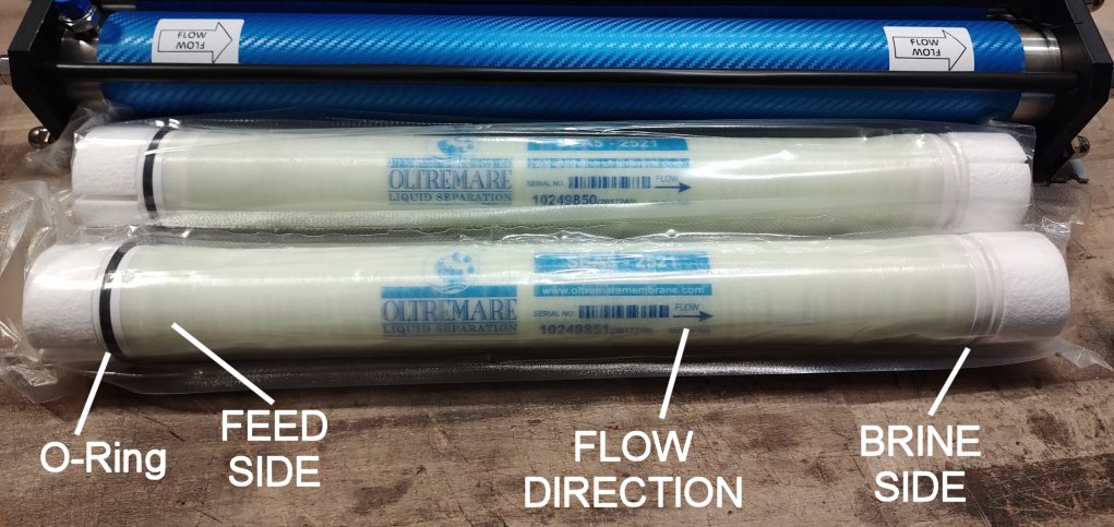
2 – Keep in mind the difference between FEED SIDE and BRINE SIDE of the vessel!

Vessel Blue Gold Watermakers vessel1 - Alte Modelle


Insert the Membrane into the Vessel

  1. First of all you must mount the head to the BRINE SIDE of the vessel.
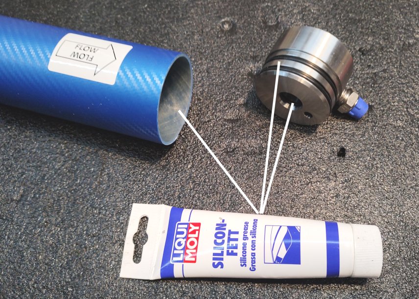
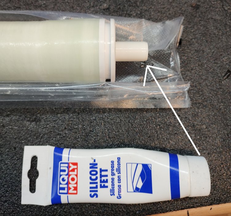
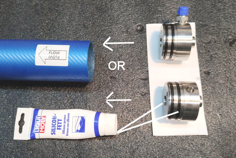
  2. Lubricate with silicon grease the O-rings of the head (internal and external) of the BRINE SIDE
  3. Lubricate with silicon grease the end of the vessel (BRINE SIDE).
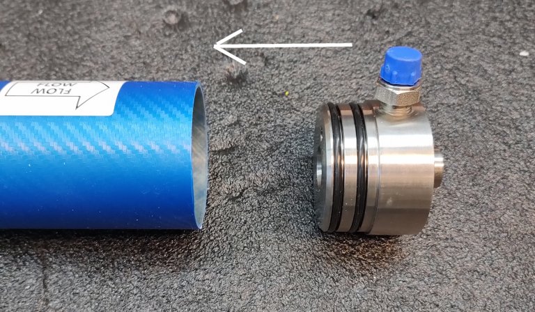
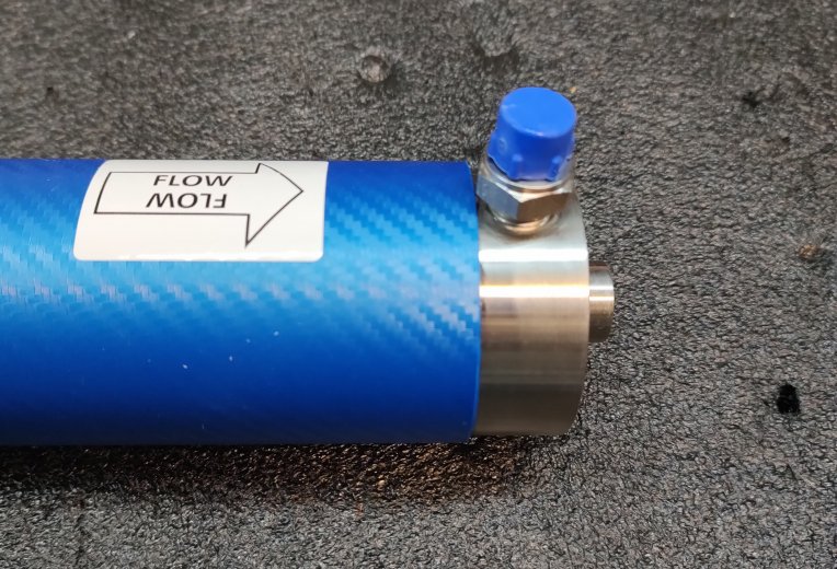
  4. Insert the head into the open end of the vessel (BRINE SIDE).Vessel Blue Gold Watermakers vessel 2 - Alte ModelleVessel Blue Gold Watermakers vessel 3 - Alte Modelle Vessel Blue Gold Watermakers vessel 4 - Alte Modelle
  5. Remove the membrane from its sealed bag.
    Once the membrane is removed from its sealed bag, the watermaker needs to be commissioned within max. 30/60 days.
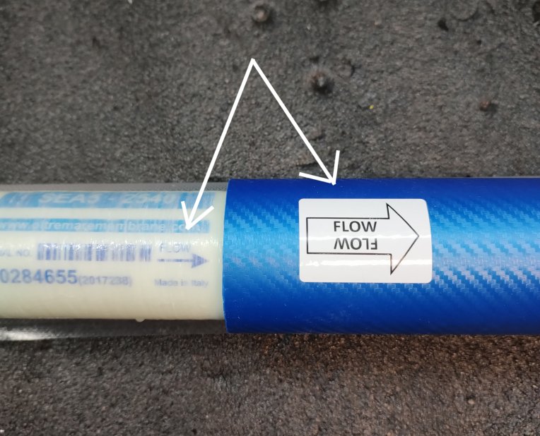
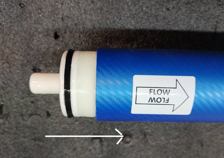
    The membrane, like the vessel, has a FEED SIDE and a BRINE SIDE, and the flow direction is as well printed on its body. The flow direction of the membrane must match with the flow direction of the vessel.
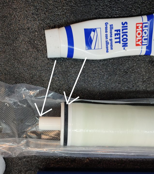
    The membrane has one only O-ring placed at the FEED SIDEVessel Blue Gold Watermakers vessel 5 - Alte Modelle
  6. Lubricate the ends of the membrane and the O-ring, and then insert the membrane in the vessel following the flow direction
    Vessel Blue Gold Watermakers vessel 6 - Alte Modelle Vessel Blue Gold Watermakers vessel 7 - Alte Modelle Vessel Blue Gold Watermakers vessel 8 - Alte Modelle Vessel Blue Gold Watermakers vessel 9 - Alte Modelle Vessel Blue Gold Watermakers vessel 10 - Alte Modelle
  7. Lubricate with silicon grease the O-rings of the head (internal and external) of the FEED SIDE.
    This head may be with or without thread, depending on the number of the vessels in the system:

    • – In a system with one vessel both the heads are threaded
    • – In a system of two vessels, both the vessels have one head with thread and one head without.
    • – In a system with three or four vessels, the intermediate vessels have both heads not threated, and the first and the last are like in two vessels system
  8. Insert the head into the open end of the vessel (FEED SIDE).
    Vessel Blue Gold Watermakers vessel 11 - Alte Modelle Vessel Blue Gold Watermakers vessel 12 e1684082076802 - Alte Modelle

Assemble the Vessels in a System of One or More Vessels

We show in the images a system of 2 vessels:

Vessel Blue Gold Watermakers vessel 13 - Alte Modelle

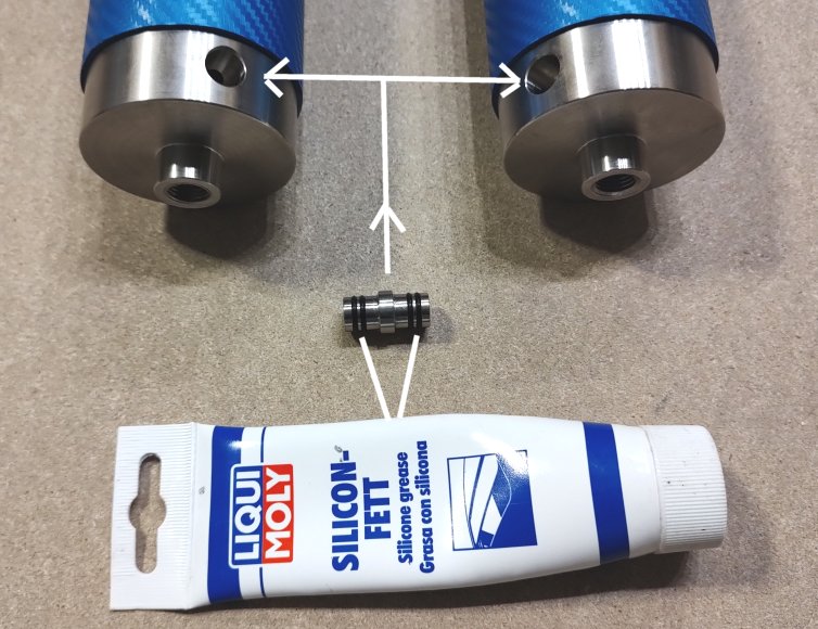
  1. Lubricate the O-rings of the special nipple and insert it into the holes of the heads.
    Now the vessels are connected each other
    Vessel Blue Gold Watermakers vessel 14 - Alte Modelle Vessel Blue Gold Watermakers vessel 15 - Alte Modelle
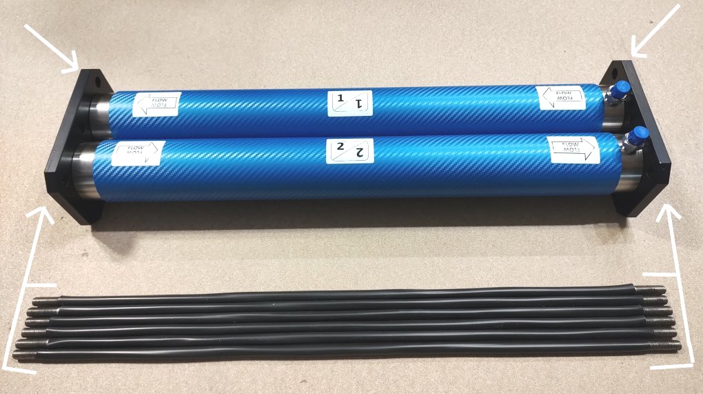
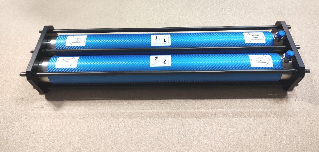
  2. Insert the heads into the holes of the plates and then insert the bars.
    Vessel Blue Gold Watermakers vessel 16 - Alte Modelle Vessel Blue Gold Watermakers vessel 17 - Alte Modelle
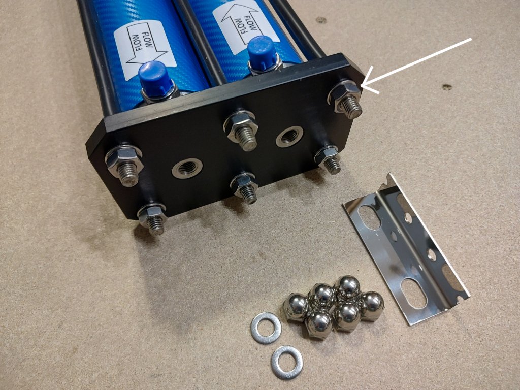
  3. Place the washers and screw the hex. nuts in both the plates. Tighten the nuts with 2 wrenches 17 mm.
    It is not needed to overtighten the nuts.
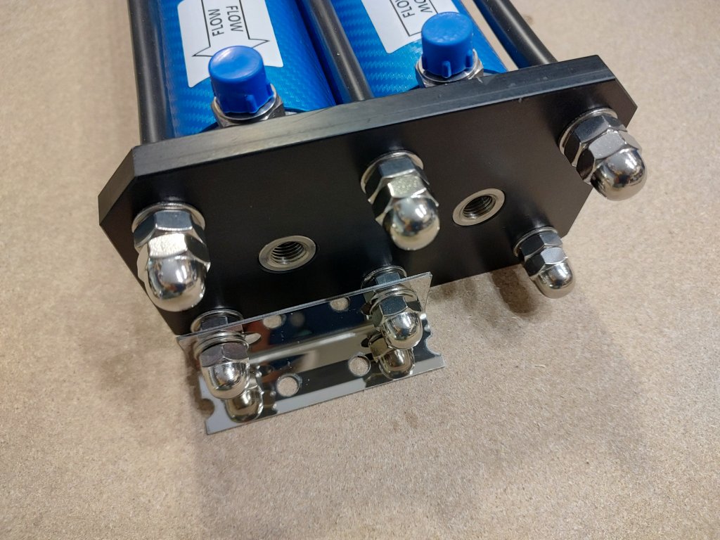
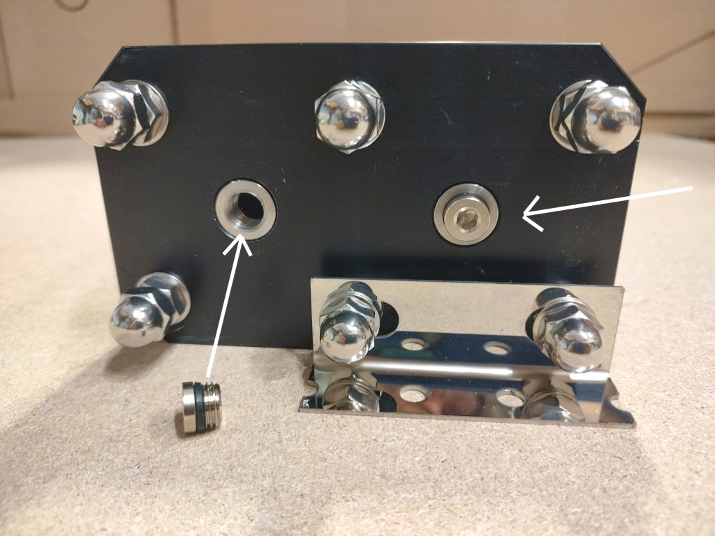
  4. Screw the blind nut and fit the inox brackets to the plates as shown in the images.
    Vessel Blue Gold Watermakers vessel 18 - Alte Modelle Vessel Blue Gold Watermakers vessel 19 - Alte Modelle
  5. Insert and screw the plugs at one side of the outlet of the permeate
    Vessel Blue Gold Watermakers vessel 20 - Alte Modelle
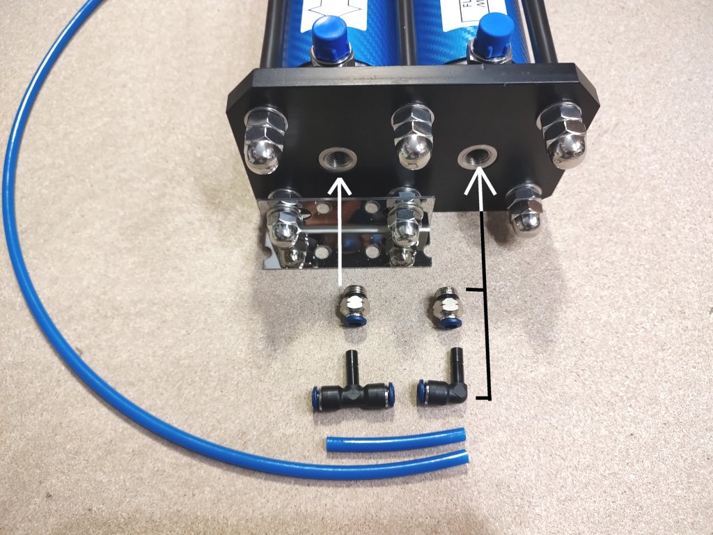
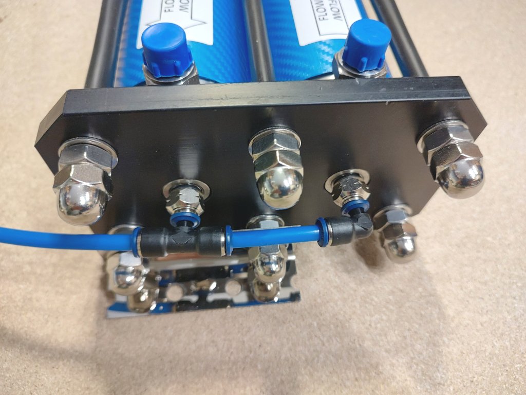
  6. Mount the quick fittings at the other side of the outlet of the permeate.
    Vessel Blue Gold Watermakers vessel 21 - Alte ModelleVessel Blue Gold Watermakers vessel 22 - Alte Modelle
  7. You got the job done!
    The vessel rack can be mounted also vertically. In this case please take care that the outlet of the permeate with the quick fittings, stands on top
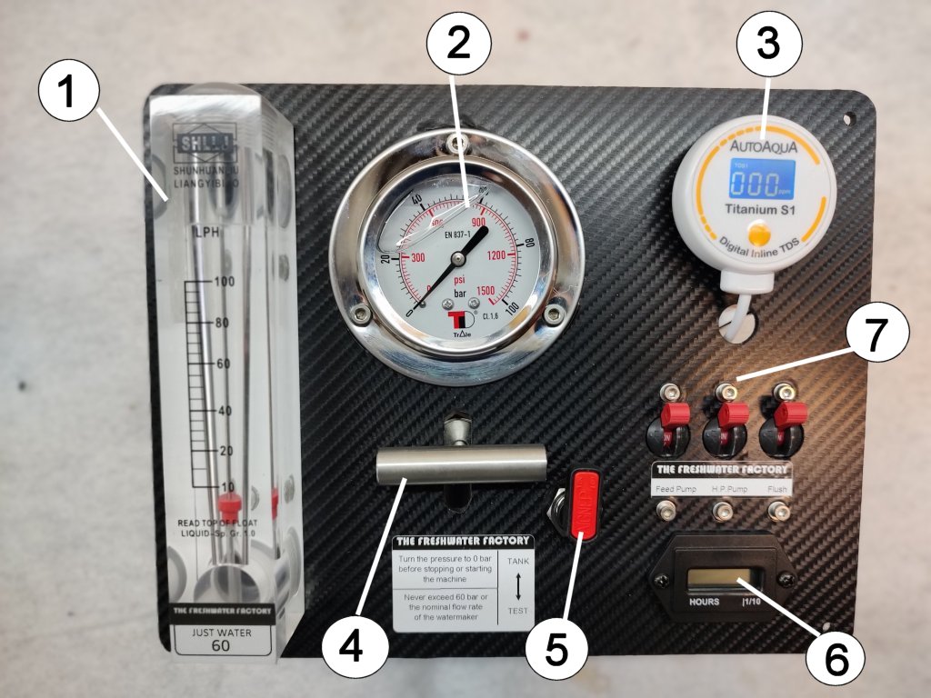
The control panel is always operated with 12V (or 24V) even in the 230V models. This for safety reasons.
No high voltage near the operator’s hands or near the water circuit.

The 12-volt models use only the panel, which directly controls the feed pump, the high-pressure pump (through a 12V relays) and the valve for flushing.In 230-volt models, the panel controls the relays of the feed pump and high-pressure pump in the switch box.

The size of this panel is 25×20 cm, but we can also prepare custom panels, matching the needs of the client.

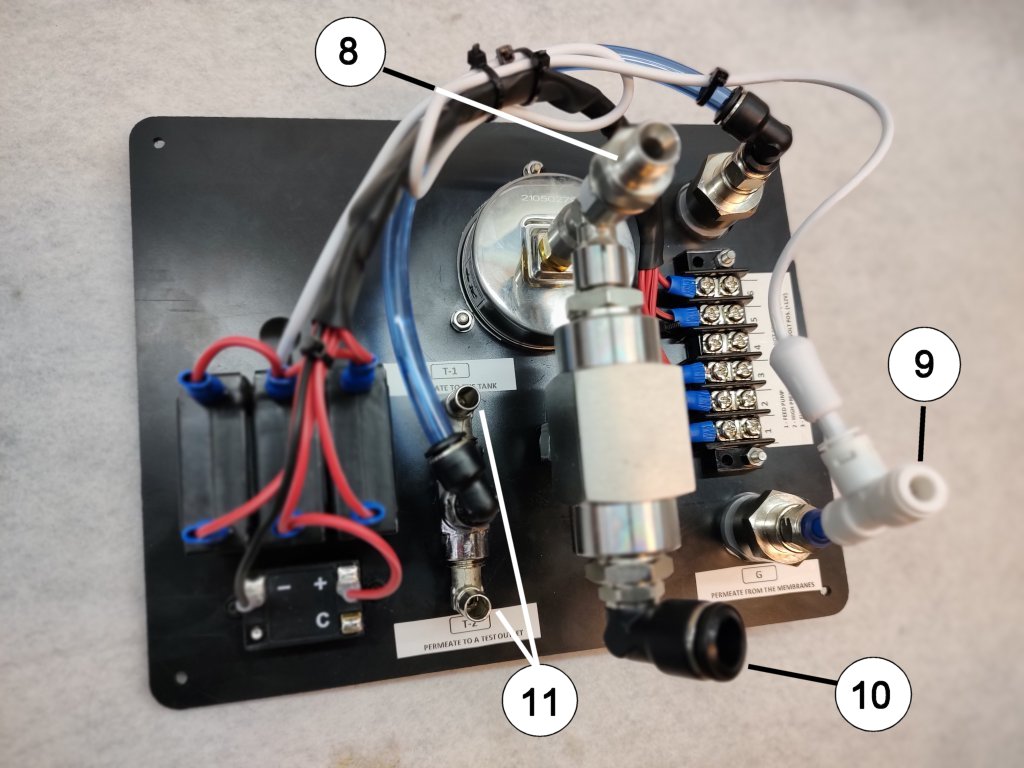
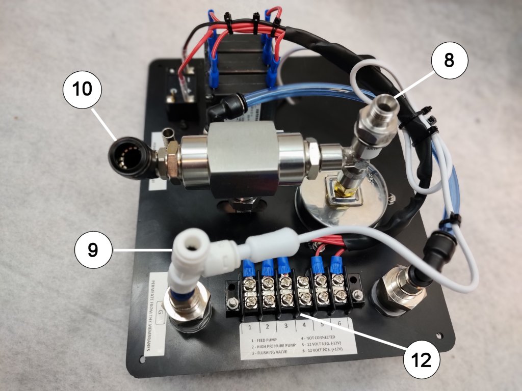
Below are some pictures of the control panel with the hydraulic connections.

Watermaker Panel Blue Gold1024 A - Alte Modelle

Watermaker Panel Blue Gold1024 B - Alte Modelle

Watermaker Panel Blue Gold1024 C - Alte Modelle

1 – Flow Meter
2 – High Pressure Gauge
3 – TDS Meter
4 – Pressure Regulation Valve
5 – 3-Way Valve for Permeate (to the tank or to a test outlet)
6 – Hour Meter
7 – Switches for the pumps and for the flushing valve
8 – Inlet of the saltwater in pressure (from the last membrane)
9 – Inlet of the permeate from the membranes
10 – Discard Water (outboard)
11 – Permeate to the tank or to a test outlet
12 – Electric connections


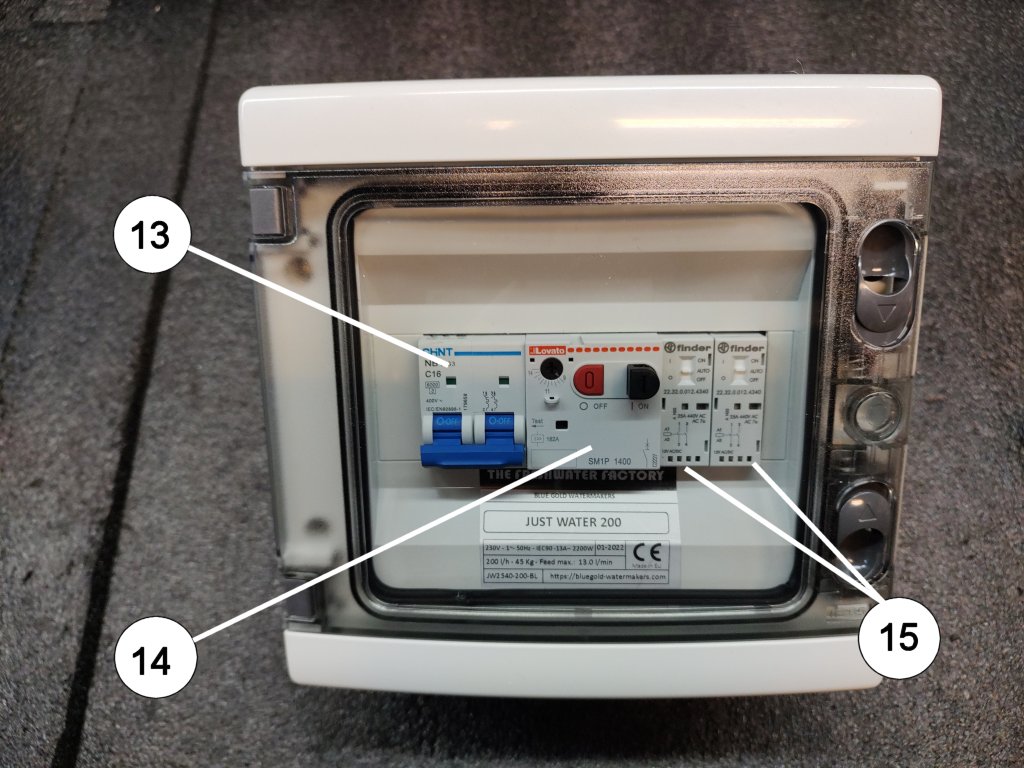
Below the switch box of the 230V watermakers

Switch box watermaker blue gold - Alte Modelle

13 – Main Switch
14 – Thermal protection for the high pressure pump
15 – Relays for the feed pump and for the high pressure pump (the coils of these relays are 12V and are driven from the switches on the control panel)


This system can work not only with our watermakers, but can be used to drive every do it yourself machine. The circuit diagram is very elementary and you can find it here


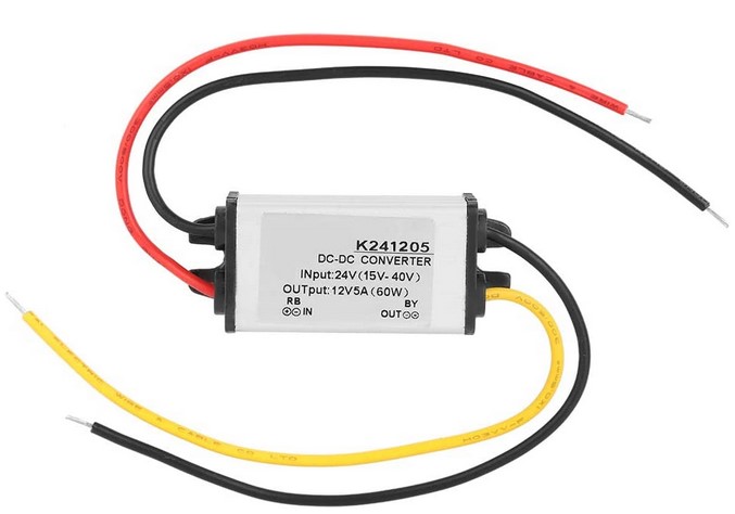
For the 24 Volt installations is delivered a 24V > 12V converter

Converter - Alte Modelle

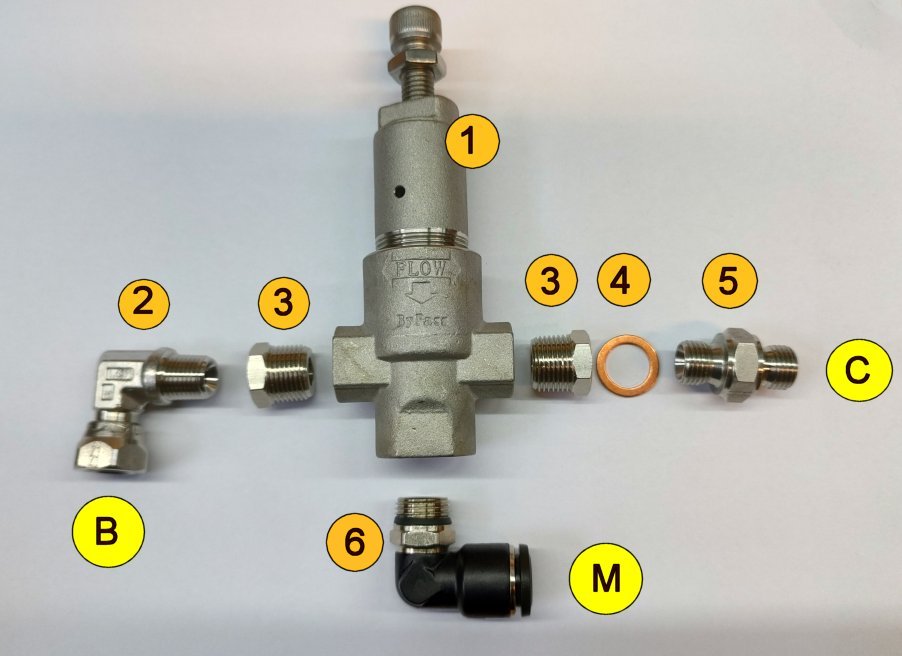
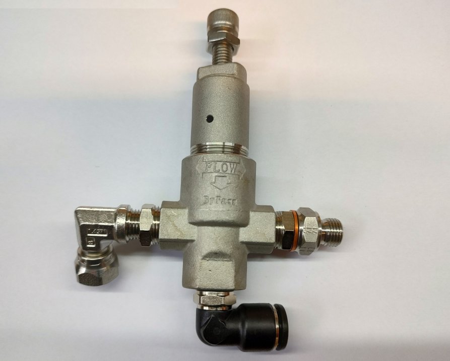
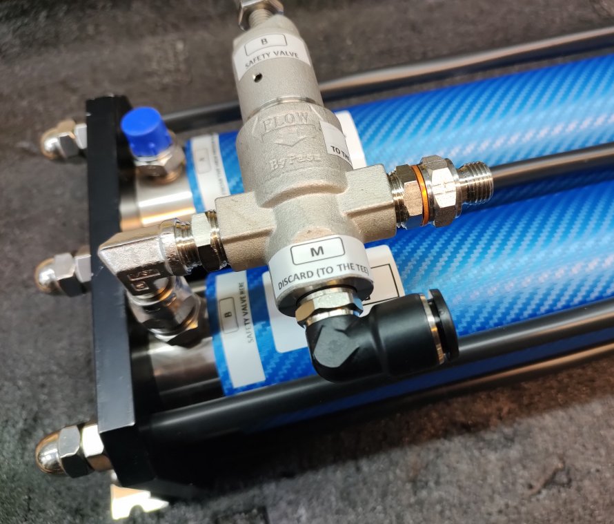
In the watermakers series PRO (with control panel) the safety valve is shipped disassembled. It can be mounted for either left or right-handed use.

Use only Teflon tape or liquid sealant for mounting.
Between the nipple (5) and the reduction 3/8-1/4 (3), do not use sealants but only the copper washer.
Also for the swiveling quick fitting (6) do not use any sealants because it is already provided with an O-ring


Blue Gold Watermakers Safety Valve Assembly 1 - Alte Modelle

B – Connection to the outlet of the last vessel
C – Connection to the high pressure hose to the panel
M – Brine/Discard outboard

1 – Body of the safety valve
2 – Swiveling fitting 1/4″F BSPP x 1/4″M BSPT
3 – Reducing nipple 3/8″-1/4″
4 – Copper washer
5 – Nipple 1/4″ M-M BSPP
6 – Swiveling quick fitting 1/4″ x 12 mm

Blue Gold Watermakers Safety Valve Assembly 2 - Alte Modelle
Blue Gold Watermakers Safety Valve Assembly 4 - Alte Modelle


Setting the Safety valve

Setup of the safety valve in a bluegold watermaker - Alte Modelle

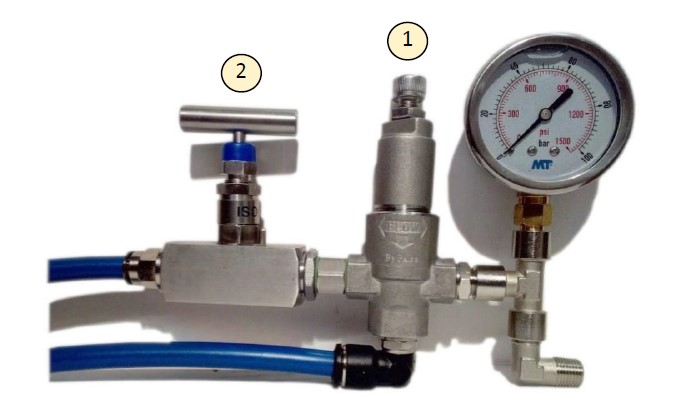
  • Open the pressure regulation valve (2) completely.
  • Open the safety valve (1) completely.
  • Start the watermaker.
  • Slowly close the pressure regulating valve (2) completely.
    The pressure should remain at 0 bar and all water is drained via the safety valve.
  • Close the safety valve (1) slowly until 68 bar is displayed on the pressure gauge.
  • Open the pressure regulation valve (2) completely
  • Switch off the watermaker.

Blue Gold Watermakers Commissioning, Regular Use, Maintenance

Reverse osmosis watermakers are sophisticated systems that demand meticulous upkeep. When product water flow decreases or TDS levels rise, some boaters who are out cruising are quick to blame the membranes. However, as we explain below, there are various plausible explanations for lower (or higher) product flow rates and TDS increasing.


Feed Water Temperature

You can quickly gauge the feed water temperature by using a basic thermometer (the thermometers in boat instrumentation are often inaccurate)

The feed water temperature has a notable impact on the flow rate of your product water. With reverse osmosis systems being rated based on feed water conditions of 32,000 ppm, 25°C (77°F), and operating at 55 bar (800 psi), it’s crucial to understand the effect of temperature on product water:
As the temperature increases, you can expect a higher TDS and a greater product flow rate. Conversely, a decrease in temperature results in lower TDS and a lower product flow rate. For instance, at 32°C (90°F), you may produce approximately 25% more water, whereas at 10°C (50°F), you could expect a 50% decrease.

In summary:
As Temperature Increases you get:
– Higher TDS
– Higher product flow rate
As Temperature Decreases you get:
– Lower TDS
– Lower product flow rate


Feed Water Salinity

You can measure feed water salinity easily with a refractometer. A refractometer is a simple-to-use device that utilizes light to measure salinity. If you don’t have a refractometer, you can consult this page that reports salt concentrations in all the seas.

Open the link by clicking on the below image, then click with the mouse on the place whose salinity you want to view

MyOcean - Alte Modelle

You can see that the salinity of the Mediterranean Sea is among the highest globally (about 38000 PPM), while it is much lower in the North Atlantic and Baltic Sea. There is also a significant differernce between the east and west coasts of the U.S.

Effect of Feed Water Salinity on Product Water:

The salinity level of feed water has a notable impact on the flow rate of product water. When the salinity is increased, the total dissolved solids (TDS) in the product water also increase, and the flow rate decreases. Conversely, when the salinity is decreased, the TDS in the product water decrease, and the flow rate increases.

If the feed water has a salinity level of 35,000 ppm, you can anticipate a reduction of approximately 10% in the amount of product water. On the other hand, if the salinity level of the feed water is 25,000 ppm, you can expect a boost of approximately 25% in the amount of product water.

In summary:
As Salinity Increases you get:
– Higher TDS
– Lower product flow rate
As Salinity Decreases you get:
– Lower TDS
– Higher product flow rate


Influence of Feed Pressure on Output Water:

Membrane test conditions are set at 55 bar, but you can safely work at 60 bar.
Don’t forget, however, that going from 55 to 60 bar increases the load on the pump motor by 10 percent, and consequently the current required and the heat that the motor must dissipate also increases.
So if you can work at 55 bar, be happy with that and do not put unnecessary stress on the motor, which is usually located in an engine room or in a confined space where the ambient temperature is already high and ventilation may be poor.

In summary:
As Pressure Increases:
– TDS is reduced
– Product flow rate is increased
As Pressure Decreases:
– TDS is increased
– Product flow rate is decreased

Productivity and Regulation of the Operating Pressure

The productivity of the watermaker is influenced by many factors, including the most important ones such as salinity and temperature of the feed water.
In brackish water, productivity tends to increase at the same operating pres-sure. Thus, the pressure must be reduced to avoid over-penetration of the membranes.

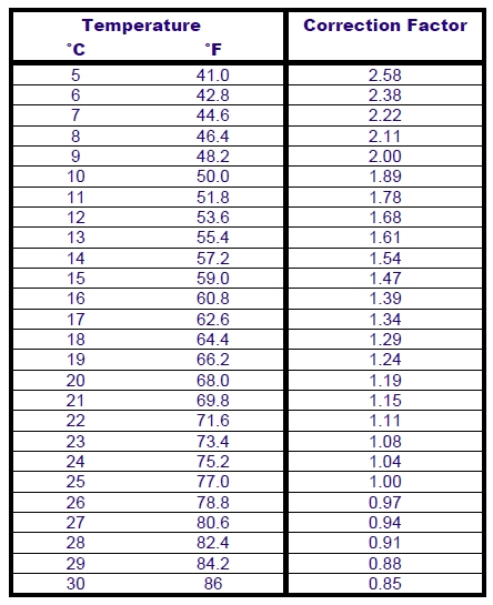
When the temperature of the feed water decreases, productivity also de-creases (see table below). In this case, the operator could increase the oper-ating pressure to the maximum allowable limit of 55/60 bar to obtain more fresh water. When the limit is exceeded, the pressure relief valve opens to release the excess pressure.
Correction factor - Alte Modelle

To obtain the theoretical amount of water produced at a given inlet water temperature, you must divide the productivity of your watermaker by the correction factor.

Example of a 60 l/h watermaker:
From a possible production volume of 60 l/h at a temperature of 25 °C, only 40.8 l/h are produced at a temperature of 15 °C.

The watermaker should be commissioned within 4 to 6 max.weeks after delivery. This is because the membranes have been removed from their vacuum-sealed packaging to be mounted inside the vessels. Do not remove the plastic plugs on the vessel nipples so that no air circulates inside the membranes.
Remove them only when you are ready to connect the high pressure hoses.

If a longer time is needed between purchase and commissioning, it is recommended to have the membranes shipped in their original packages and insert them into the vessels at the time of assembly. Alternatively you can operate a “Long Term Preservation” procedure, as described in the Maintenance section.

Checking the installation for leaks and functioning

  • Open the seawater valve.
    If you have installed a non-self-priming feed pump, make sure that it is also flooded.
  • Turn the pressure regulation valve counterclockwise until it is fully open.
  • Switch on the system with the main switch.
    It may be useful to fill the system beforehand. A short fresh water rinse by the onboard pressure pump will fill the system.
  • Switch on the feed pump.
  • Switch on the high pressure pump (pressure 0 BAR).
  • Check that the seawater is drained.
  • Bleed the system
    Vent the system by allowing it to operate depressurized.
    If there are air bubbles in the feed circuit, the high-pressure pump will run noisily and not smoothly.
    Do not increase the pressure as long as there are air bubbles in the line between the feed pump and the high-pressure pump.
    If the high-pressure pump is well supplied with water and the water regu-larly runs out of the outlet, you can increase the pressure.
  • Slowly turn the pressure regulation valve clockwise until 40 bar is displayed on the pressure gauge.
    Allow the system to operate for a few seconds to release air from the circuit. The first produced water should now run out of the permeate hose.
  • Slowly turn the pressure control valve clockwise until 55/60 bar is displayed on the pressure gauge.
    While doing this, watch the flow meter. Depending on the salinity of the seawater, either the maximum pressure or the maximum flow rate of your watermaker will be reached first.

IMPORTANT

  • Do not exceed the maximum operating pressure of 55/60 bar, even if the nominal productivity of the watermaker is not achieved.
  • Do not exceed the maximum production capacity of the watermaker.
  • Check the system for leaks each time you run the watermaker.

Setup of the safety valve in a bluegold watermaker - Alte Modelle

Setting the safety valve

  • Open the pressure regulation valve (2) completely.
  • Open the safety valve (1) completely.
  • Start the watermaker.
  • Slowly close the pressure regulating valve (2) completely.
    The pressure should remain at 0 bar and all water is drained via the safety valve.
  • Close the safety valve (1) slowly until 68 bar is displayed on the pressure gauge.
  • Open the pressure regulation valve (2) completely
  • Switch off the watermaker.

Now the watermaker is ready for producing freshwater.
Do not forget that the water produced in the first 1/2 hour needs to be discharged because of the preservative solution present in the membranes.

Starting the watermaker

  • Open the seawater valve.
    If you have installed a non-self-priming feed pump, make sure that it is also flooded.
  • Turn the pressure regulation valve counterclockwise until it is fully open.
  • Switch on the system with the main switch.
    The sistem should be already filled with seawater and almost no air bubbles should be in the circuit
  • Switch on the feed pump.
  • Switch on the high pressure pump (pressure 0 BAR).
  • Check that the seawater is drained.
    Vent the system by allowing it to operate depressurized.
    If there are air bubbles in the feed circuit, the high-pressure pump will run noisily and not smoothly.
    Do not increase the pressure as long as there are air bubbles in the line between the feed pump and the high-pressure pump.
    If the high-pressure pump is well supplied with water and the water regularly runs out of the outlet, you can increase the pressure.
  • Slowly turn the pressure regulator valve clockwise until 40 bar is displayed on the pressure gauge.
    Once the high-pressure pump is running smoothly, you can increase the pressure.
    Do not increase the pressure as long as there are air bubbles in the line between the feed pump and the high-pressure pump.
    If the high-pressure pump is well supplied with water and the water regularly runs out of the outlet, you can increase the pressure.
  • Slowly turn the pressure control valve clockwise until 55/60 bar is displayed on the pressure gauge.
    While doing this, watch the flow meter. Depending on the salinity of the seawater, either the maximum pressure or the maximum flow rate of your watermaker will be reached first.

IMPORTANT

  • Do not exceed the maximum operating pressure of 55/60 bar, even if the nominal productivity of the watermaker is not achieved.
  • Do not exceed the maximum production capacity of the watermaker.
  • Check the system for leaks each time you run the watermaker.

The watermaker is now producing freshwater


Ending the production and flush the watermaker with the Easy Flushing System

  • Turn the pressure regulator valve counterclockwise until the pres-sure gauge indicates 0 bar.
  • Let the watermaker run for a couple of minutes depressurized.
    This causes the removal of the accumulated salt on the mem branes.
  • Switch off the high pressure pump.
  • Switch off the feed pump.
  • Switch on the Easy Flushing System.
    The automatic pressure pump of the boat will start. Allow the system to flush for the time needed.
    Refer to the “Easy Flushing System” tab, to simply discover how many time is needed.
  • Switch off the Easy Flushing System.
    The automatic pressure pump of the boat should stop
  • The watermaker is flushed.

IMPORTANT

  • While flushing the watermaker, the feed pump and the high pressure pump must be OFF.
  • If the watermaker is used daily, you can flush it every 2 or 3 days.

Ending the production and flush the watermaker with manual flushing

  • Turn the pressure regulator valve counterclockwise until the pres-sure gauge indicates 0 bar.
  • Let the watermaker run for a couple of minutes depressurized.
    This causes the removal of the accumulated salt on the mem branes.
  • Switch off the high pressure pump.
  • Switch off the feed pump.
  • Position the 3-way flush valve to the “Flush” position.
    The automatic pressure pump of the boat will start. Allow the system to flush for the time needed.
    Refer to this topic to simply discover how many time is needed.
  • Set the 3-way flush valve back to the initial position.
    The automatic pressure pump of the boat should stop
  • The watermaker is flushed.

IMPORTANT

  • While flushing the watermaker, the feed pump and the high pressure pump must be OFF.
  • If the watermaker is used daily, you can flush it every 2 or 3 days.

Membrane Storage Procedure

The composite polyamide type of the membrane elements must NEVER be exposed to chlorinated water.
Any such exposure will cause irreparable damage to the membranes.
Absolute care must be taken following the preparation of cleaning or storage solutions to ensure that no trace of chlorine is present in the water. Use ever distilled water or permeate water to carry out the operation.

The storage procedure is divided in three chapters, based on the duration of the storage:

  • Short-term storage of the membrane elements in place in the vessels.
  • Long-term storage of the membrane elements in place in the vessels.
  • Dry storage of the membrane elements as spares or before assembling a watermaker.

Short-Term Storage (Maximum 30 days)

Short-term storage is for periods where the watermaker must remain out of operation for more than five days, but fewer than thirty days, with the membranes in place.

  • Flush the watermaker with de-chlorinated water, while simultaneously venting any air from the system.
  • When the vessels are filled, close the appropriate valves to prevent air from entering the system.
  • Reflush as described above at 5-day intervals.

Long-Term Storage (Maximum 6 months)

Long-term storage is for periods where the watermaker must remain out of operation for more than 30 days with the membranes in place.

  • Flush the watermaker with permeate water or in any case with de-chlorinated water
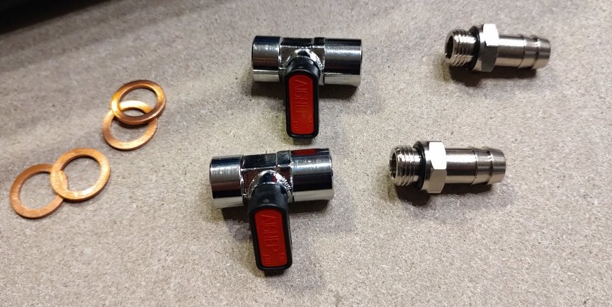
  • Mount if our kit for preservation:
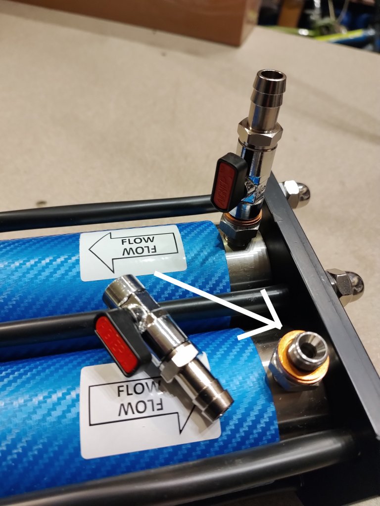
    – Remove the high pressure hoses from the inlet and the outlet of the membrane rack (In the “LIGHT version do not remove the high pressure unit at the outlet because the regulation valve will do the same work of the second valve of the kit)
    – Mount the two valves as shown in the images. Use 2 copper ring each valve. Close them and tighten slightly with a wrench.
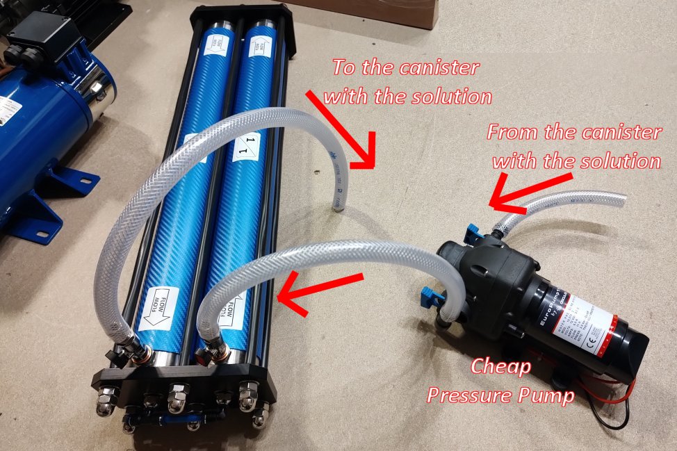
    – Connect the hose to the automatic cheap pressure pump provided and to a 10 liters canister where you will prepare the preservative solution.
    – You have created a closed circlepreservative kit 1 - Alte Modelle preservative kit 2 - Alte Modelle  preservative kit 3 - Alte Modelle
  • Prepare 10 liters 1% SMBS (Sodium metabisulfite) solution. This means 100 gr. in 10 liters of distilled water or permeate water as told above.
    Every 2540 membrane contains 1.5 liters of water and every 2521 membrane contains about 1 liter of water.
    So add to the solution 15 gr of SMBS every 2540 membrane of your watermaker, and 10 gr every 2521 membrane.
  • Wire the pump to a 12 Volt source, open the valve at the outlet of the membrane rack and then open the valve at the inlet. The pump will start.
  • Recirculate the solution for a few minutes
  • Close the valve at the outlet of the membrane rack and soon after the valve at the inlet (If you have a “Light” version close the completely the needle valve and then close the valve at the inlet).
  • The vessels are now filled with preservative solution and no bubble of air should be inside. Check for drops/leaks. Flush the cheap pressure pump with some freshwater.
  • Flush the system and replace the solution every 90 days if the temperature is below 25°C, or every 30 days if the temperature is above 25°C.
  • When the watermaker is ready to be returned in service, remove the valves, clean them, reconnect the high pressure hoses, flush the plant and then start it. Discard the water produced in the first 30 minutes.
  • With this system the solution os SMBS does not flow through the other components of the watermaker and the two valves ensure that the system does not empty or air enters
  • Of course you can also arrange a similar system with your own fittings, the goal is that the vessels remain filled with solution and that the air does not enter.

Storage before installation

When RO/NF elements are stored prior to installation, they should be protected from direct sunlight and stored in a cool, dry place with an ambient temperature range of 5°C to 35°C
New Elements are enclosed in a sealed polyethylene bag containing a storage solution, and then packaged in a cardboard box.

Note: we have a quite big turnover of membranes, so they are never old. We recommend to use the new membranes within one year from the purchase.

Prefilters

Prefilter Blue Gold Watermakers - Alte Modelle

The filter elements must be installed to protect the high pressure pump and the reverse osmosis membranes.

The service life of the filter elements is closely related to the type of inlet water. It is recommended to change the filters every 50/100 hours of operation.
When you remove the filter, you may notice that the color of the inner part of the cartridge is greyer than the outer part. The filter cartridge should never turn completely grey, it should be replaced before this happens.

Do not use washable filters, as they may be accidentally damaged during washing. If they are damaged, their efficiency will be compromised and the warranty for the pump will be voided.
Always use disposable polypropylene melt blown type filters with a filtration efficiency of at least 85%.

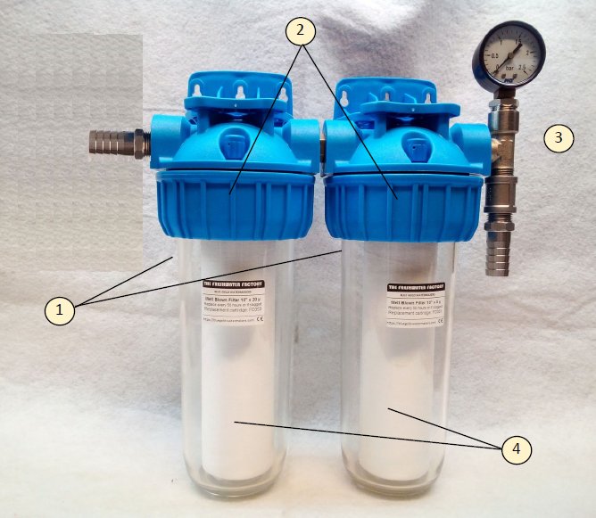
  • Loosen union nut (2) completely using the wrench and remove the bowl (1) downwards.
  • Empty the bowl in a bucket and remove the used cartridge (4).
  • Insert the cartridge (4) into the respective bowls.
    Note, the first filter is 20 micron, the second filter is 5 micron. In the smaller versions there is only one 5 micron filter.
  • Grease the O-rings of the bowls with silicone grease. This facilitates the mounting.
  • Insert the bowls in the correct order and fasten them with the union nut by tightening it with the wrench.

If you plan a long downtime of the watermaker empty the circuit from the water and do not fit the new cartridges until you need to use the watermaker again.


Carbon Filter

blue gold watermakers activated carbon filter - Alte Modelle

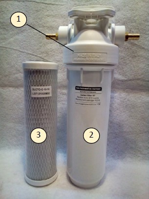
During the flushing, the activated carbon filter protects the reverse osmosis membranes from chemical elements, such as chlorine, which would destroy them.
Replace this filter at least every 4/6 months.

  • Unscrew the bowl (1) with the wrench, empty it in a bucket and remove the old cartridge (3).
  • Insert the new cartridge
  • Grease the O-rings of the bowls with silicone grease. This facilitates the mounting.
  • Screw again the bowl in the head of the filter housing
  • Fasten it by tightening with the wrench